"Programmer Electronic Control"
PartNo. 51-019-02, NSN 1680-99-652-3410,
Supplier K0656, Marconi Avionics, UK
Alternate designation (unsure!) NSN 5865-99-977-8365, Part No. 51-048-02
(Restoration of a vintage rugged computer from the Tornado aircraft)
With reference to and the historic context of
the Elliott 900 series in general
and the 12/12, 920M and 920ME in particular.
Left to right: 12/12 (From NCS1 gyrocompass, 12bit), PEC (102 from Skyshadow with ECM
panel, 12 bit), 920M on top of 920ME (Jaguar, 18 bit),
AFDS with panel (Tornado, 12 bit)
Partnumbers of the 18bit machines: 920M: IL322A11787, NSN7440-99-111-8581
and 6930-99-111-8581; 920ME: 75D28482.
- The complete Story in pictures, by Erik Baigar, www.baigar.de -
erik@baigar.de
 News/History
5.6.2020: Major update to reflect the acquisition of two 920Ms, their
restoration and more results,
including updated wanted items ;-) - My
Elliott collection is fairly complete now!
10.6.2017: Added the Impressum to
the index (to serve the new DSGVO-EU).
10.6.2017: Fixed typos, complete update of the
logbook 2015-2017
and Elliott stuff included here directly.
Contents...
- Results of the reverse engineering efforts on PEC
- Logbook listing the major steps of the last year
- Roots of the unit / architecture
- Suspected original use (!Needs Update!)
- Other applications of the 12 bit Elliott 900 series
- Elliott, GEC, Marconi: Historic Context
- The "full size" 18 bit 920s: The 920M and 920ME
- Simulation for 12bit and 18bit Elliotts
- External information
- Items Wanted - not only Elliott stuff
- MANY THANKS
- Picture "gallery"
- Older history
- Impressum
1. Result of the reverse engineering efforts on the PEC from 2004 until today:
Starter of the whole avionics/vintage computing hobby was the acquisition of
a small black box named "PEC"; over several months I reverse engineered its
functions, created a setup to program and run it and wrote an assembler to
generate programs for it; the result was a first...
Command reference of the "Programmer Electronic Control"
...in which I described and named the commands. This contains lots of technical information,timings, pin-outs and much more. Publishing this led to the feedback, that the machine belongs to the
Elliott 900 series, starting a long journey which still goes on ;-)
Current status: The 12-bit processor
is fully operational running my own "tiny-OS"- even interrupts and the IO system
are working now.
A "hello world" is perfectly running on an attached LCD display and the unit can
control a CalComp M84 pen plotter drawing an image of itself.
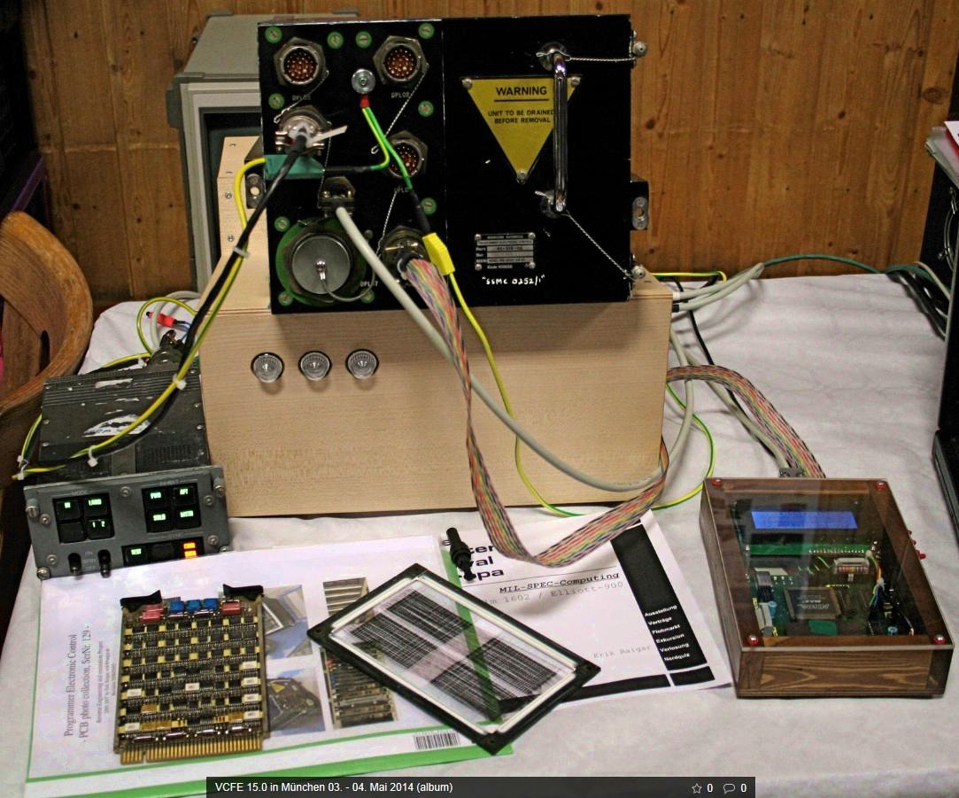

Photo Suite of all the printed circuit boards of the unit:
(1) Driver Board, 1680-99-646-6754; (2) Data Board, 1680-99-646-6755; (3) Core Memory, 5841-99-652-3386;
(4) Driver Board, 1680-99-646-6754; (5) Control Board, 1680-99-646-6753; (6) Data Register, 229-013909;
(7) Data Register, 229-013909; (8) Control Register, 229-013551; (9) Function Decode, 229-013549;
(10) Processor Timing, 229-013547; (11) RxTx Interface, 229-013545; (12) Serial Parallel Converter, 229-016304;
(13) Decode and Interrupt, 229-013905.
The unit consists of 15 boards of standard size 100mm*160mm, containing a
total of 497,
mainly standard mil-spec TTL 54XX chips. All of them are
identified, even the exotic four
custom ones and data-sheets are available. Here is a
Collection of
technical information
on all chips used in the PEC's processor including statistics of the date codes.
The next milestones in my hobby is to finish the blinkenlights for the
Programmer Electronic Control:
Paper tape, teletype simulation,
word generator and register display are working and SAP already runs
nicely. Missing is control of single stepping, run/stop and memory
access via the PEC-OMP
(PEC-Operators Monitor Panel).
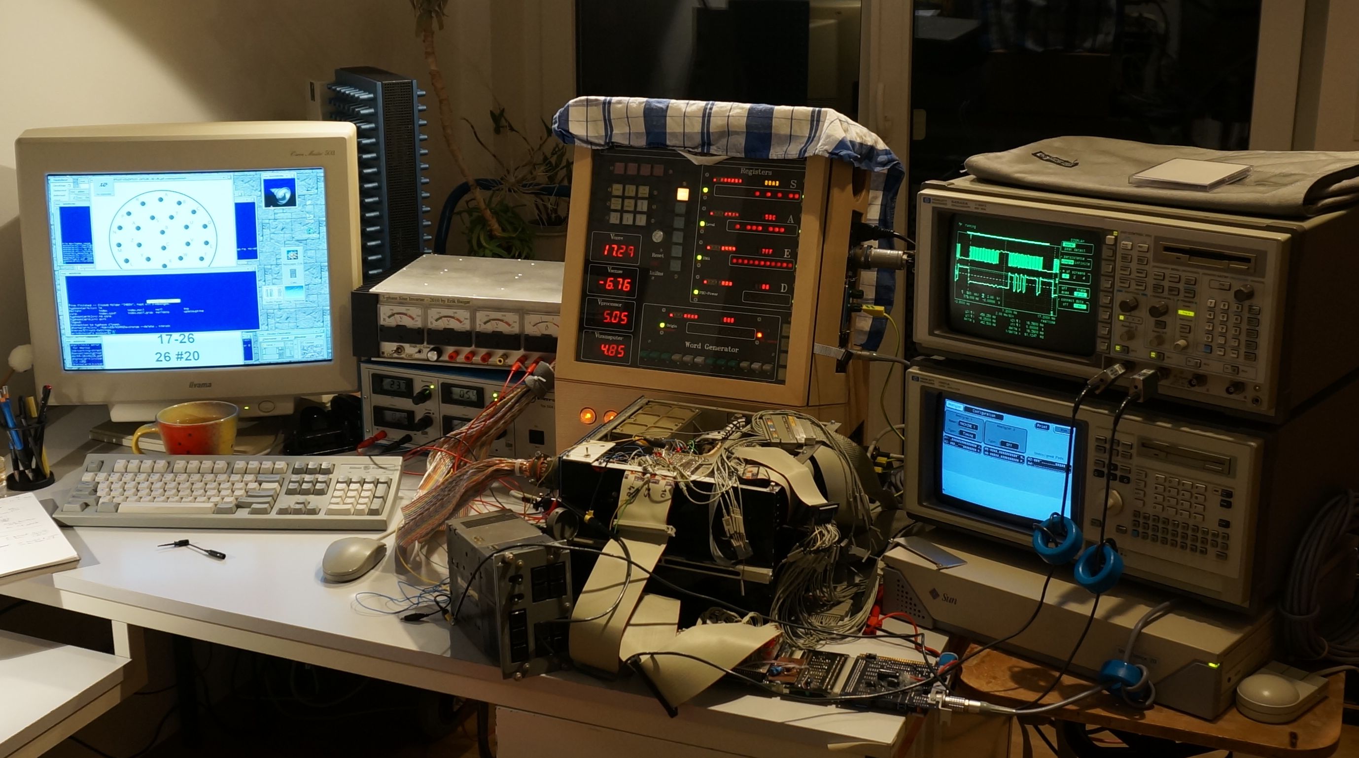
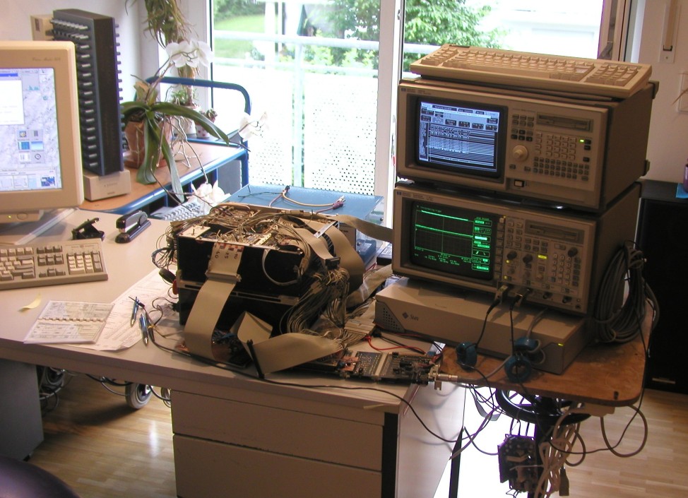
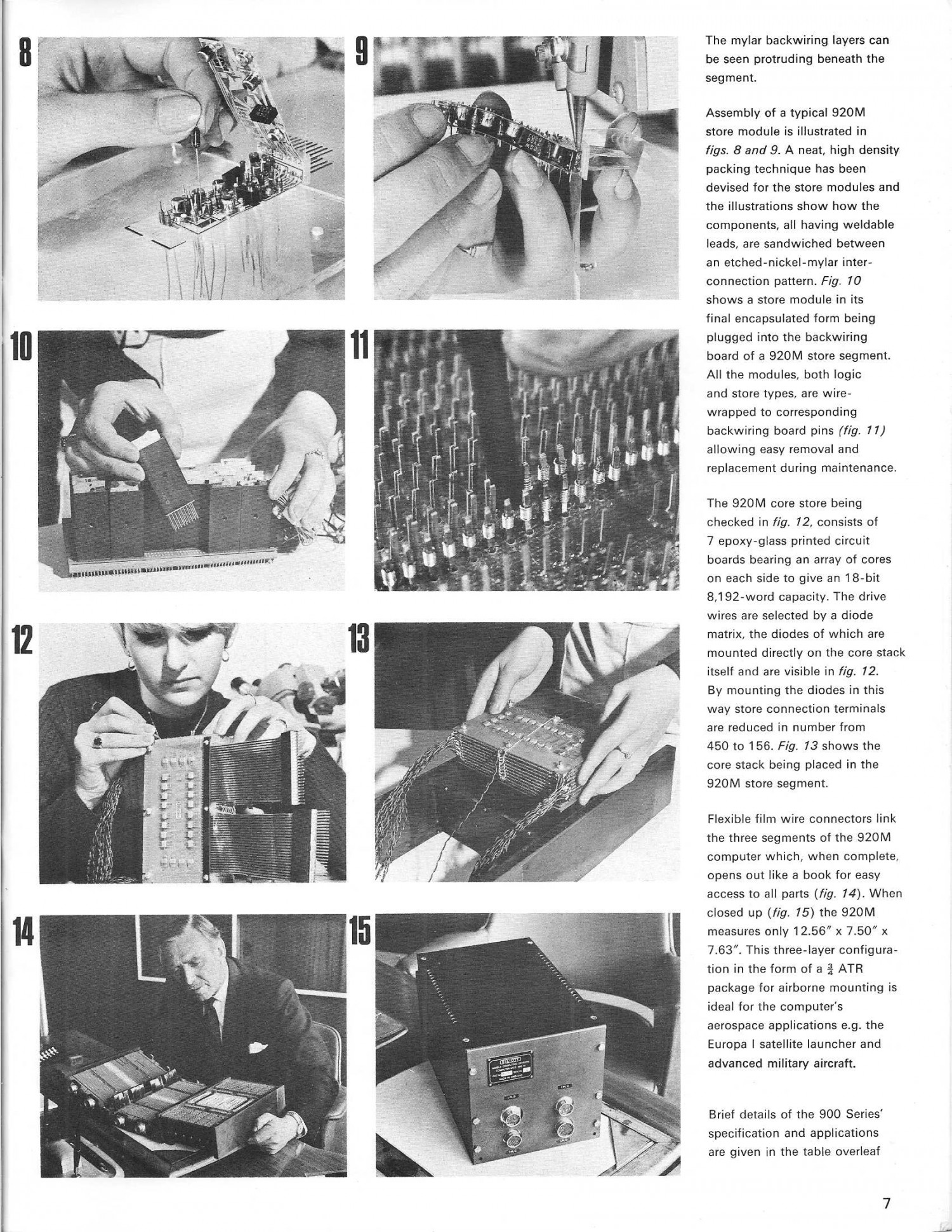
Current (5/2017) view of the setup: All components including Sun Sparc 20, PEC, logic
analyzer and the homebrew OMP are installed on a movable cart to ease storage:
![[pics/PECsetup201705.gif]](pics/PECsetup201705.gif)
 : Old setup (4/2014) with original panel from Tornado
connected for the first time.
: Old setup (4/2014) with original panel from Tornado
connected for the first time.
2. The Chronology of the Elliott 900 project...
...starting in 2004 is a longer story. Thus, the complete diary is located on a separate page, listing all major stepsand achievements during the years of reverse engineering: TimeLine. This page contains and explains
many of the pictures shown in the gallery below.
In the more recent years many other marvels of engineering of the 1970ties attracted my
attention and led to
exciting analysis-, restoration- and documentation-projects. All these are
listed in the TimeLine,
but the
latest achievements from this logbook
related to the Elliott 900 series are the following:
DATE |
ACTIONS |
PICS |
| 3/13/2017 |
First analysis of the 920ME showed, that the ME's supplies both deliver 5V
to two different nets on the backplane. One of the supplies did not work
and I had to fix it - herein I noticed, that it contains a manual patch,
changing its output from 3.3V to 5V - so probably the chassis of the
ME is adapted from an other application where a processor with 3.3V
CPU voltage was used. After some reverse engineering I had identified data- and address busses to the RAM as well as the control signals; I connected a logic analyzer to these signals, showing that after power up there is indeed activity and that the machine starts at 8177 (octal) as is expected from a 18 bit 900 series machine starting without initial instructions (II) engaged. Of the three front plugs, only SKH has got an easily removable cap which can be "parked" next to the plug. So my assumption was, that this must be the plug for a loading unit and hopefully the machine provides a paper tape interface there. Again after some reverse engineering I identified 8 digital input lines, 8 digital output lines and a hand full of handshake signals. Experiments showed, that one of the signals forces the microcode of the unit to write II to store right after power up and to launch them at 8181. Via two other signals one can send data byte per byte to the initial instructions. After initial excitement I noticed, that after three words got written to store the machine runs havoc. Investigation showed, that during execution of the II, the instructions are not read from store (although having been written there during startup), but access to the II is trapped by microcode. After the first three words have been written to store, the II transfer control to the newly written words at 8177 and this failed as reading from store did not work correctly (For an explanation of the II in the 900 series, see PAGE7). After a longer search I discovered defective 54138 chips in the memory controller. Later I found an additional such chip in an other subsystem causing problems there and as all had the same date-code I assume that there was a problem unique to exactly this series of the part. Anyhow, after fixing this, loading software worked well for some small self made examples ran nicely! I discovered, that SKH also serves for paper tape punch and teletype in/output via the additional handshake signals. In the weeks following and in preparation for the CCSs visit, I built an interface emulating a paper tape station and teletype via the 920ME's SKH plug offering hard coded paper tapes one can select from, an USB interface with parity/telecode conversion for teletype and an additional RS232C port for a real paper tape device. This makes my 920ME an complete 900 series 18 bit computer now! |
![[920ME-BateryReplacement.JPG]](920ME-BateryReplacement.JPG)
![[920ME-Debugging.JPG]](920ME-Debugging.JPG)
|
| 6/4/2017 - 8/4/2017 |
A delegation of the Computer Conservation Society
(CCS) visited Munich after
they met Horst Zuse in Berlin. I had the opportunity to join them for dinner on
Friday and in a guided special tour in the Deutsches Museum. It was great to get
in touch with many highly skilled computer experts - the achievements of the CCS in preservation,
spreading and reconstruction of vintage computers in the UK are
indeed outstanding! On Sunday Terry (also CCS member) visited me in Aubing, where we played with PEC and after a demonstration of the FIN1010 inertial navigator we focused on working on the 920ME: Terry had prepared some clever tests to find out whether the 920ME has additional commands implemented (i.e. 905 command set), how the Q register is treated, whether the memory is OK, what side effects there are in instruction 14 (shift) and he also had some nice demos with him. During the tests we had to discover, that there still is a memory problem if there are plenty off accesses to store. So the memory test failed and e.g. the solver for the count down game being a popular television series in the UK fails giving wrong answers! In summary, the 920ME does not have got the 920 ATC command set implemented and it does not have the floating point or stack extensions within its microcode. But it obeys all 920M commands correctly making it a direct replacement! So the session was a full success, leaving me with some homework to do and lot of new software to explore. Looking forward to get the original 900 series BASIC Terry wrote in the late 1960ties running on the ME... |
![[CCS-DtMuseum2.JPG]](CCS-DtMuseum2.JPG)
|
| 5/22/2017 |
In hunting the memory problem of the 920ME
computer I discovered, that it needs an additional supply voltage to drive
the memory subsystem (during all experiments until now, this supply was
just 1.5V instead of 5.0V simply supplied from the protection diodes
within the address driver chips of the memory subsystem). Although in my opinion it is a design flaw, that the machine starts without this voltage being present, I am happy that it is now working perfectly: Several hours of memory test do not show any issues any more and the software I got from Terry works simply great: BASIC, a solver of the count-down game and CORAL programs compiled externally run if loaded via my paper-tape/TTY simulator interface. So the 920ME is a machine being compatible to the 920M (with some additional not yet clear functionality) running at the speed of the later 2us-store version of the 920M from the later 1960ties. Although using rather new components (e.g. 2901 as DG Eclipse) the "ME" machine is one of my slowest computers as microcode reduces speed to be compatible with the original 920M. Probably this machine was designed as a replacement for the Jaguar's NAVWASS system to eliminate the need to support the aging DTL technology of the 920M any longer. Many thanks to Terry Froggatt for his steady and highly appreciated support with this project - it was and always still is great to learn from him! Thanks also to Allen Vernon from the Bentwaters Cold War Museum where he works on the restoration of Jaguar XX741. |
![[920ME-AUXsupplyPatch.jpg]](920ME-AUXsupplyPatch.jpg)
![[920ME-InterfaceFinal.jpg]](920ME-InterfaceFinal.jpg)
|
| 1/8/2020 |
Restoration work on the 920Ms started by investigation and documentation.
Removing the skin to get access to the folded three blocks (Two with small
logic modules and one with bigger ones for core memory which is enclosed in
an environmentally protected and sealed compartment). Connection between the
blocks is by multiple thin Mylar sheet cables which end in connection
modules mounted onto the main boards like all others, too. After the many years, removing the screws was quite hard and required drilling them out in two cases. After that the machines can be folded open nicely like a book! In applying power to 5328, everything seemed normal first with below 50W power consumption. A first test with II activated and applying power good indeed showed the machine asking for data after around 40us. But fun did not last very long as 5328 soon developed highly increased power consumption which I traced town to a failure in the core store section. But as all the small modules are wrapped to the mainboard on 18 pins, and they are potted with some transparent adhesive, there is no chance of easy repair of the individual modules. So I decided to go the easy route first and continue with the 2nd machine with serial number 5358. But unfortunately this developed a short after a few correct attempts to load data via initial instructions... |
![[920M-UnfoldedLogicModules.JPG]](920M-UnfoldedLogicModules.JPG)
![[920M-Unfolded-WireWrap.JPG]](920M-Unfolded-WireWrap.JPG)
|
| 2/17/2020 |
920M: Experiments with 920M #5358 showed, that the PLA pin 15 - although it is
not connected to the other +5V pins as listed above - still needs to be
powered to make the memory work! It is required by the core system. This also explains an oddity I encountered in working on 920ME 2018: This required a resistor to power an additional power rail feeding the CMOS RAM. In not doing so, ME`s memory did not work under heavy load: I did not connect this rail to 5V properly, but just fed it by the added resistor (and the protection diodes of the RAMs without the resistor). I made this mistake in 2018 because I thought that ME, which has heavy and nice supplies built in generating 5V internally, does not need an additional external 5V supply. Lesson learned ;-) Meanwhile the battle against failing modules goes on and using the milling machine reveals the innards of more of the modules, here a 33F module containing filtering for core drivers and 30F with an inhibit driver and read amp... |
![[920M-33Funleashed.jpg]](920M-33Funleashed.jpg)
![[920M-30Funleashed.jpg]](920M-30Funleashed.jpg)
|
| 3/27/2020 |
920M, #5358 seems to present all oddities possible: For three weeks
parts where dying faster than I have been able to understand, debug and
swap modules. In parallel, Terry is ringing through his 5343 and creating
very valuable documentation, and we are having excellent discussion to
fully understand the core system which is source for various problems. A logic analyzer for the USB port comes in handy to supervise lot of signals in parallel, where for documentation an oscilloscope is much better. Clearly seen can be the typical waveforms (logic 0...5V and core signals -5...18V) of #5358, where the digital signals show the behaviour typilcal for DTL ( diode-transistor-logic): Fast falling edges followed by slow rising ones. These signals are hard for modern logic equipment like the LogicPort analyzer to trace correctly. There have been a short in a sense amplifier (module type 30F) followed by several broken filter modules for the core driver lines (type 33F) and also line driver module with one branch shorted to Vcore. Debugging of shorts was most easy using the thermal camera of my CAT phone, but some problems needed watching signal forms and detective work, using the emerging understanding and documentation. Deep respect for the men and women who did all the wire wrapping (approx. 400 modules in there, making more than 10000 wire wraps in total) and unwrapping drives me crazy: (1) Some of the wire warpings are done in the wrong direction and my manual tool can not unwrap these properly. (2) The connections are not wire-to-pin, but two pins are wrapped together by a short piece of wire; in unwrapping, the wire tends to cram the tool resulting in twisted pins making it hard to reuse and warp in the module into a new location. With faulty modules from #5358 (replaced by cannibalizing machine #5328) accumulating I wanted to know what is inside... Using my small milling machine I opened some modules - the potting can be polished, so one can nicely look into the modules: PCBs had not been invented when the 920M was developed in the 1960ties, instead thin sheets from Mylar with the traces on it where used and the arrangement of the components was three-dimensional (between sheets and on the sheets). As the Mylar easily melts at temperatures used during soldering, the components where welded (not soldered) to the traces! Really a strange technoloy and I wonder whether the concept of potting is really that good, given the mismatch in thermal expansion coefficients. The mainboards are more than 7mm tick and there are surely >10 sheets stacked over each other to implement the complex wiring between the only 35 different module types. In this short clip showing Kosygin visiting the Elliott factory, one can shortly see some of the ingredients of the mainboards and modules right after the unfolded 920M. Two pages from an Elliott document show more details: 1 2. |
![[920M-5358-Debugging.jpg]](920M-5358-Debugging.jpg)
![[N8#01.gif]](N8#01.gif)
|
| 4/15/2020 |
After one more faulty 33F and a K6 module and more analysing, finally the
920M
got more stable and on 3/25/2020, 20:42 machine #5358 for the first time
executed some simple programs loaded via the initial instructions!
! SUCCESS - Elliott MCS.920M, #5358 operational !An old price list states, that even in quantity the DTL chips where over 10USD each, making only the semiconductors a big investment in these machines especially given the value of the USD in those days. Analysis of all the logic modules and drawing schematics would be possible (same potting used, so one can look in if unwrapped), but following the traces is not easy as the Mylar sheets are in two or three layers. X-ray does not help to unfold the connections :-( Important lesson learned: The pulses for acknowledging data transfers on the paper tape and TTY ports need to be shorter than the execution time of the read instruction, e.g. 15 2048, as the signals are level and not edge sensitive. Pulses of 5us are perfect - for longer ones (say 20us), the 2nd stage loader fails as it reads the same byte twice. Programs like tic-tac-toe and the processor tests executed easily! Only the memory test program XSTORE still leads to strange crashes of #5358... |
![[920Mruns_20200325_210715.jpg]](920Mruns_20200325_210715.jpg)
![[920M-LogicModule.JPG]](920M-LogicModule.JPG)
|
| 4/21/2020 |
Today a second 920M, serial number 5343 executed its first 3-word programs. I
donated this machine to Terry Froggatt from the
CCS last year and now I am
pretty sure, we have in total two good 920Ms running: 5358 on my side and
5343 in the UK. 5328 with lot of modules removed stays on my side as spare
part box. Statistics on two machines confirms, that to operate a "M", the power supplies should be capable of delivering +18V@2A, +12V@1A, +5V@6A and -5V@1A as average current. This will be sufficient even for a dynamic stop or heavy computation.
|
![[KitTerry_20200320_185529.jpg]](KitTerry_20200320_185529.jpg)
![[PlugTerry_20200320_185348.jpg]](PlugTerry_20200320_185348.jpg)
|
| 4/21/2020 |
After more fine-tuning, the new panel/supply setup works nicely and
the problem with
the XSTORE crashing the 920M is resolved, too (an increased power is
drawn on the +12V line during hefty memory accesses and the current limit
of the LTC3780 module was to paranoid - additional caps or increasing
the set current resolve the issue) -> 920M serial nomber 5358 is
completely operational. Following was a phase of consolidating the setup, assembling everything into the Homing panel, plotting inserts for the panel so the push buttons show what they do. Also some documentation and data sorting was necessary, should weird problems show up in the future. The Arduino powered panel can now store up to 99 paper tapes in its flash memory and one can be loaded on the fly into its RAM. The digi-keys on the front allow selection of two tapes which are fed into the machine one after another (e.g. BASIC and than a program like tic-tac-toe). Push buttons allow selecting whether TTY and paper tape are routed to USB or to the two serial ports on the rear side and various code translators (telecode, CR/LF) can be selected on a rotary knob as well as run/stop/test/debug-level modes. For future use (i.e. completely driven by a computer via USB), there can be activated a parser on the USB port overriding the front panel settings. The LED displays show which tape (left/right) is active and how many percent of it have been loaded by the machine already. Documentation now consists of around 100 oscillograms from the core memory system and signals to the logic blocks as well as some recordings with the logic analyzer of the II (Initial Instructions) in action. Terry generated lot of tables as documentation of inter-module wiring - THANKS for all the fruitful discussion! |
![[920Mruns_20200325_210733.jpg]](920Mruns_20200325_210733.jpg)
|
| 4/21/2020 |
Up to now, the pins where not mounted in the milled inserts. Unplugging
is no problem with the rear plugs, as the thick cables allow pulling the
insert and all sockets out easily by pulling on the cable.
But the front plug the cables are to fragile and I used to pull back the
insert and remove the pins individually. As this is not cool, I glued the
pins into the inserts 3 to 5 at a time and seating the plug back in the machine
for curing to ensure proper alignment. In one of these steps, I contaminated
pin 25 with adhesive, so the whole thing stuck on the computer and upon
pulling harder, the socket came out of the machine with the pin :-( Replacing the plug (and swapping with the spare machine) would require removal of the whole mainboard and heavy wire wrapping work. After noticing, that a short piece of the wire to the socket is still present deep within the computer, I decided to glue the pin back in with two adhesives: Conducting silver adhesive for the back side and standard 2 component epoxy for taking the mechanical stress. So far the pin is back in and I have a signal on this pin 25 (data from machine to PTP/TTY)... |
![[920M-5358-PinRip.JPG]](920M-5358-PinRip.JPG)
![[920M-5358PinAdhesives.JPG]](920M-5358PinAdhesives.JPG)
|
| 4/26/2020 |
After some cleaning up I checked whether the new panel and power supply
also work with the 920ME computer: Yes, they do. Observed the following
difference: In contrast to 920M, which exposes the accumulator
all the time on its rear plug PLC (LSB: 9, 7, 5, 6, 13, 8, 60, 12, 57, 61, 53,
58, 59, 54, 11, 15, 10, 14: MSB) for use by external devices
via the IO commands, the "ME" just updates these lines during IO commands.
But this was to be expected because of ME being based on the AMD29XX
chips which hold the accumulator in the chips, so it can not be exposed
externally easily and it is not necessary to do this for use of
"ME" as replacement for "M" which got un-repairable. Also I unwrapped some more modules from 920M#5328 to have some spares and most of the logic modules contain circuitry (like flip-flops) made from 15946 quad dual-input-NAND gates. 12 gates per module maximum and there are also modules with just resistors and the cable connections are implemented as modules with flexible Mylar PCBs coming out at the side for connection of the three blocks to each other. |
![[920M-5328-LogicModuleRecovery.jpg]](920M-5328-LogicModuleRecovery.jpg)
![[920M-5328-CoreModuleRecovery.jpg]](920M-5328-CoreModuleRecovery.jpg)
|
| 6/5/2020 |
The journal
Resurrection
of the British Computer Conservation Society
(CCS)
in its latest issue includes
90
an article by Terry Froggatt on our common restoration work the 920Ms: On my side
machines #5358 and #5328 plus #5343, which I donated
to Terry. Apart from my #5358, Terry's #5343 is now up and running with
certain restrictions, too.
Hoping to send some spares to Terry soon, so he can fix his "M".
Additional interesting reading, all by Terry in the reporting section on the society's activity, can be found in Issue 72 on the de-classification of the original application software which ran on the 920M computers: The flight program from the Jaguar fighter jet. My work on the 920ME and the resulting discovery of a bug in the math software WORKSHOP which was undiscovered for over 45 years is referenced in Issue 80. Terry even "released" a fixed version of the software after disassembling the code. |
|
![[920ME-Interface-20170316.gif]](920ME-Interface-20170316.gif)
![[920ME-LogocAnalyzer-Interface.JPG]](920ME-LogocAnalyzer-Interface.JPG)
![[920ME-Repair0.jpg]](920ME-Repair0.jpg)
![[Setup920ME-X3tests.jpg]](Setup920ME-X3tests.jpg)
![[TerryErik-WorkOn920ME.JPG]](TerryErik-WorkOn920ME.JPG)
![[Elliott900implementations.gif]](Elliott900implementations.gif)
![[920M-5358opening.JPG]](920M-5358opening.JPG)
![[920M-5328-CoreSection.JPG]](920M-5328-CoreSection.JPG)
![[920M-30Fremoval.jpg]](920M-30Fremoval.jpg)
![[U2#28.gif]](U2#28.gif)
![[920M-BadlyUnwrapped.JPG]](920M-BadlyUnwrapped.JPG)
![[920M-F30-ModuleMilling.jpg]](920M-F30-ModuleMilling.jpg)
![[920M-F30-ModuleOpened.jpg]](920M-F30-ModuleOpened.jpg)
![[33F.gif]](33F.gif)
![[TI1966-PriceList.gif]](TI1966-PriceList.gif)
![[920M-5358-CoreII.gif]](920M-5358-CoreII.gif)
![[920M-ME-PT-TTY-Panel.jpg]](920M-ME-PT-TTY-Panel.jpg)
![[920M-ME-PanelRelabeling.JPG]](920M-ME-PanelRelabeling.JPG)
![[920M-ME-PanelPlotting.JPG]](920M-ME-PanelPlotting.JPG)
![[920M-ME-PanelPlotted.jpg]](920M-ME-PanelPlotted.jpg)
![[920M-5358PinReglue.JPG]](920M-5358PinReglue.JPG)
3. What are the roots of the unit / architecture...
Talking to experts involved with the computer company Elliott
(later GEC-Marconi, Marconi Avionics
and today BAE systems), based in the UK, it was
possible to identify the box by comparison of the command set:
The "Programmer Electronic Control" similar to the 12/12 from Elliott.
This is a downsized 12-bit variant of the bigger 18-bit machines of the Elliott 900series, delivered beginning in 1961. For information on these (e.g. the 920), look at the
"Our Computer Heritage" project of the Computer Conservation Society documenting
British computers.
The following documents have been carefully preserved for over 30 years by
Terry Froggatt and I am really happy that he shared them with me:
The 12-12 essentially is a repacked version of the deskside Elliott 902,
which was optimized for size, power consumption and the other needs of
airborne computing. Following are a picture and the detailed command
description of the "full size" Elliott 902 (compare them to
mine :-) ):
 902 Facts Card (compare with
equivalent for the 18bit variant:
902 Facts Card (compare with
equivalent for the 18bit variant:
 ).
).
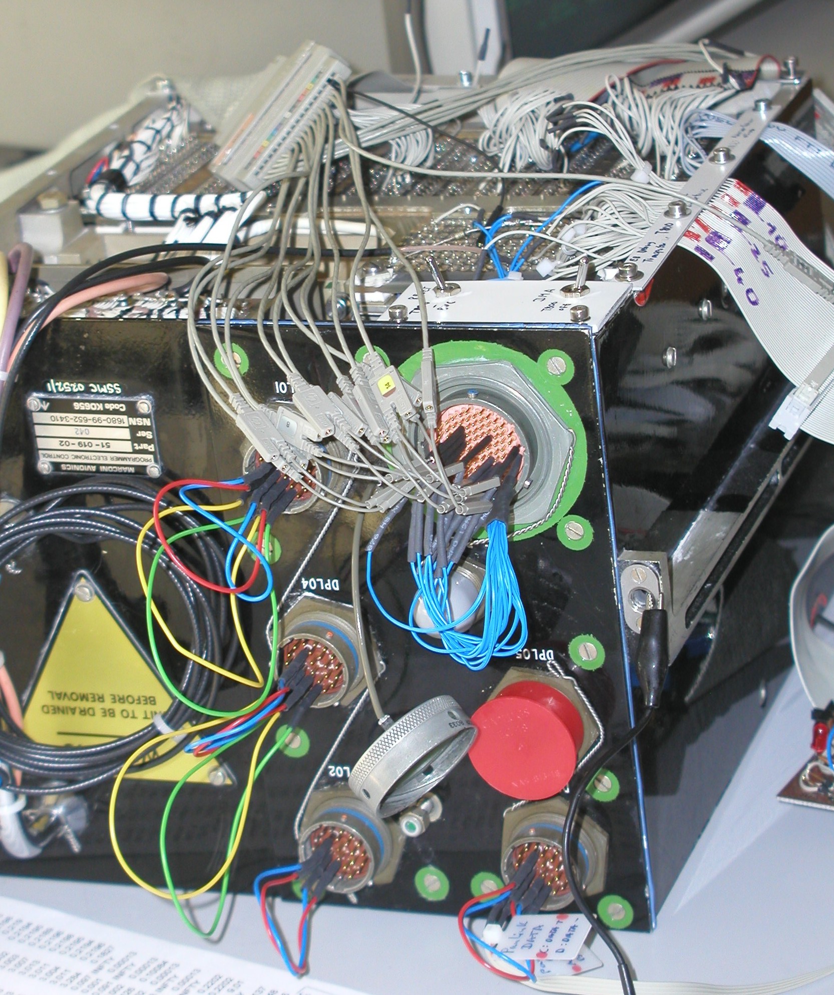
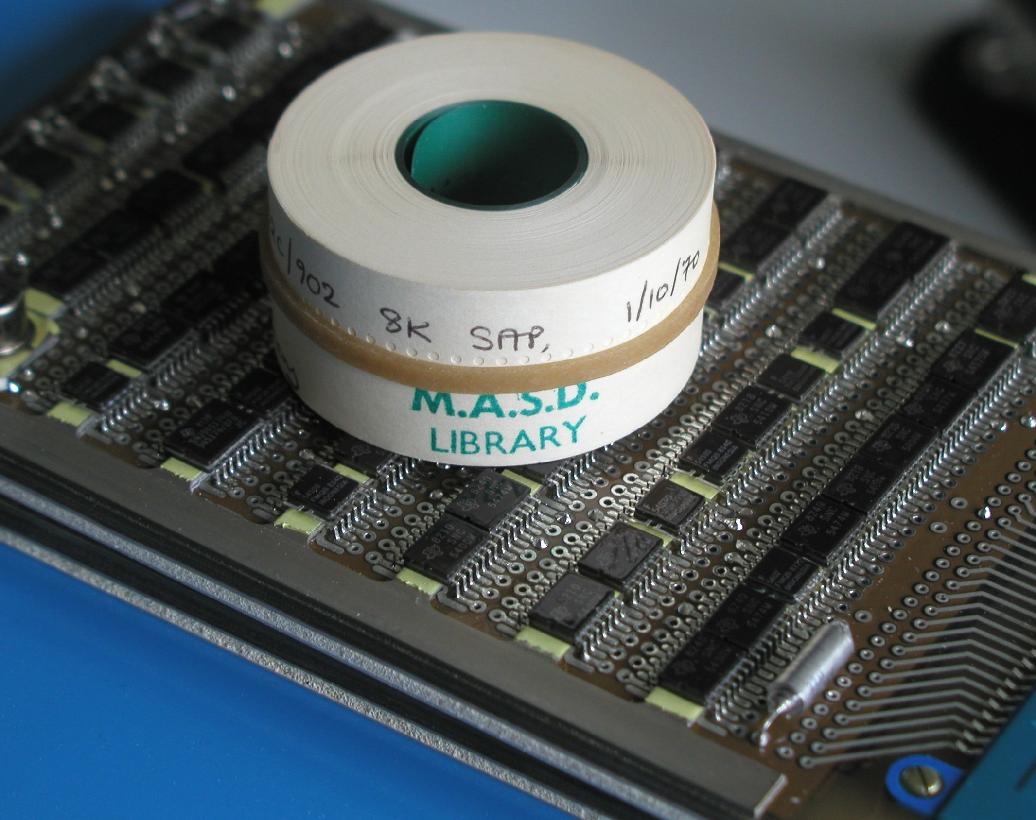
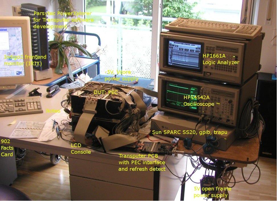
The following pictures show the early (6/2008) setup of the Programmer
Electronic Control on my bench with and without explanations. In the
last
picture you can see an original paper tape (dated 1/10/1970) sitting on
a PCB of the PEC. I got this from Terry Froggatt, too and it contains the
ORIGINAL
assembler for the Elliott 902 called SAP or "Symbolic Assembler
Program":
 with explanations
 with explanations
IRQ bridged
with explanations
IRQ bridged
On 5/3/2014, joining the VCFe 15.0 in Munich I introduced the Elliott-900 series
in a 45min talk to
the audience and an exhibition compared
the US made Rolm MIL-SPEC series based on the
Data General
architecture to the Elliott 900 (Sorry, German language only!).
Poster -
 VCFe 15.0
 - Slides
4. Suspected original use of the unit...
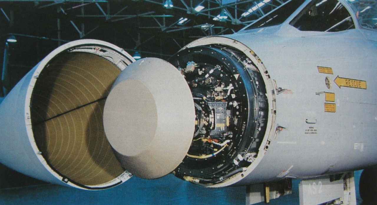

![]() Avionics specialists suspect that the Programmer Electronic Control was part of the
Avionics specialists suspect that the Programmer Electronic Control was part of the
first models of Tornado ADV's Foxhunter AI24 radar set.
According to the timeline, the PEC
might have been used in Stage1 and before and thus probably
was retired in 1991.
![]() In Foxhunter there was no 12/12 - already in the first
versions, the radar data processor
In Foxhunter there was no 12/12 - already in the first
versions, the radar data processor
was a
920ATC
(Advanced Technology Computer). Instead, rumors tell me, that the PEC was used in the
Skyshadow
self-defence system carried within a pod on the left outer pylon in the
Gr.1s. According to the
Internet it was phased out in the 1990ties during the midlife update of the pod and
replaced by a 68020 based box.
There must have been "core store loaders" for in field programming of the
units (i.e. rugged paper tape
readers) and "operator data panels" (blinkenlights) for service. But my fear is, that documentation
and all other
artefacts are long gone...

Any information, hardware, hints, pictures and discussion is absolutely welcome,
please contact me at erik@baigar.de.
5. Other applications of the 12 bit Elliott 900s...
The PEC's cousin, the Elliott 12-12 computer, was used in various applications starting in the
1970ties and some may still be online today! One example of it's use is the auto-throttle computer
of the Boeing 747-100:
![[pics/12-12.jpg]](pics/12-12.jpg)
![[pics/Minim-Autothrottle.jpg]](pics/Minim-Autothrottle.jpg)
The AFDS, the Auotopilot and Flight Director System, forms a vital part of the Tornado's
avionics.
These two redundant computers (Part.Nos. 49-134-01 and 49-133-01) control automatic flight of the aircraft
at very low altitudes since its first flight in 1974 using input from the inertial navigator and other sources.
The
two redundant computers are EPROM programmed 12 bit machines based on the Elliott 900 architecture are using
CMOS RAM with parity and probably will remain in service until the last Tornado will have gone out of service -
which will be as late as 2020:
![[pics/AFDS-System.gif]](pics/AFDS-System.gif)
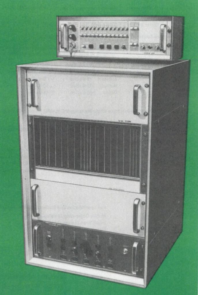
Last but not least, the architecture was used for non airborne applications, e.g. the DCU (NSN 6605-99-529-3906,
Part.No. CD 11660) was used in a gyro compass system called NCS1 which was installed on many ships...
![[NCS1-DCU-1.JPG]](NCS1-DCU-1.JPG)
In this application, the 12 bit Minim unit has a program in small ROMs together with calibration constants
for compensating the gyroscope's errors in the system. So the architecture is in use for over 50 years
now and surely there are still many more applications I do not know of .... any hints are welcome!
6. Historic context of the Elliott machines (12 and 18 bit)
The following diagram shows a timeline of computing with focus on MIL-SPEC computers
of Elliotts and the rivaling company Rolm (later Loral) from the US. For reference, some
other well known, now vintage, computers and events are listed. The machines from Digital
Equipment are widely known in the "community" whereas the Data General machines form the civil
counterpart to the military Rolm machines (the early variants ip to the Eclipse are binary compatible):
It can be seen, that Elliott has been in the business of computers for a very long time before the other companies
even started their activities where they accumulated lot of experience with analog mechanical computers,
differential analyzers, analog computers and early digital computing - they where among the pioneers of computing!
So they made already computers from 0st to 3rd generation before microprocessors entered the field.
The architecture of the Elliott 900 machines spans the era from 2nd generation computers (1960, i.e. use
of single transistors and magnetic memory) in the early implementations e.g. of the early 903 up to 3rd gen.
computers (i.e. LSI circuits; thanks to Terry Froggatt for permission to use the 903 pictures):
![[pics/903-PCB.jpg]](pics/903-PCB.jpg)
![[pics/903.gif]](pics/903.gif)
The latest machine of the series I know of, is my 920ME acquired in 2016 via eBay, which
implements the architecture
using LSI chips centered around the AM29xx series of the late 1980ties and thus is
clearly a 3rd generation implementation
of the architecture (see also next chapter):
![[pics/920ME-PCB.jpg]](pics/920ME-PCB.jpg)
![[920ME-16kStore-CompleteMachine.jpg]](920ME-16kStore-CompleteMachine.jpg)
Throughout the over 20 years of the evolution of the 900 series, it is highly interesting
to note size reduction in the
transition from transistor based implementations occupying several fridge
sized cabinets like the 905 to the miniaturized
versions like the 920M using the first
chips in DTL technology (TTL or CMOS have not been invented by than). The story continues
to the "ME" above or the even smaller PEC using tiny MIL-SPEC SMD packages:
18 bit, Transistors 905: ![[pics/905.gif]](pics/905.gif) ;
12 bit, 902:
;
12 bit, 902: ![[pics/902.gif]](pics/902.gif) and
PEC using DIL/SMD:
and
PEC using DIL/SMD:
![[pics/PEC-PCB.jpg]](pics/PEC-PCB.jpg)
![[pics/PEC.png]](pics/PEC.png) .
.
Summarizing the various implementations of the 900 series architecture and their specifications leads
to the following chart where clickable pictures of the machines are repeated below the chart for reference:
![[920M-MCM7-1.jpg]](920M-MCM7-1.jpg)
![[Unfolded2.gif]](Unfolded2.gif)
![[920ME-BlackBox.JPG]](920ME-BlackBox.JPG)
Left to right, i.e. chronological order:
903, 920M, 920M unfolded, 902, 905, PEC, 920ME
The machines of the 1960ties are all based on ferrite core memory where the later ones use
CMOS RAM for storing program and data.
It is interesting to note, that the ME despite being some 15 years "younger" than the 920M, runs at the
same speed. The implementation is artificially slowed down by the microcode: Instead of the 150ns cycle
time easily possible with the hardware given, it runs at 10 to 20 micro seconds and thus is one of my
slowest computers. Probably this was done to make it a direct replacement for the 920M used in the
NAVWASS system of the
SEPECAT Jaguar aircraft as the
original 920M's technology was
not
maintainable anymore in the 1980ties and Oman operated the Jaguar using "ME" until 2014 - meaning,
the Elliott 900 series was airborne for over 47 years!
Last but not least I doubt, there is any other architecture out there, having that
log history and having been part
of the computer development from transistors
down the road to LSI chips....anyone wants to contradict?
7. The 18 bit, mil-spec 900 machines: The 920M and 920ME
920M (IL322A11787 / NSN7440-99-111-8581 - in use probably 1967-2011):
In the mid 1960ties first integrated circuits became available and not only in the US peoplewhere working on air/space borne computing, e.g. the Apoolo Guidance Computer (AGC),
but also in the UK activities where started to re-implement the military 920B transistor computer which
was used in Forward Artillery Control Equipment ( FACE) and in the Nimrod Mk 1 submarine hunting aircraft.
The result was the 920M, shoebox-sized equivalent, which was used from the late 1960s in the
Inertial Guidance System of the ELDO Europa Satellite Launcher, and in the Navigation &
Weapon Aiming Subsystem (NAVWASS) of the SEPECAT Jaguar aircraft.
![[NAVWASS-BlackBoxes.jpg]](NAVWASS-BlackBoxes.jpg)
![[900Mstack.jpg]](900Mstack.jpg)
In a
happy moment 2019 I got hands on three of these 920M computers, one of which
I
donated to Terry Forggatt in the UK. Using spares from the second I, finally
was able to fire
up the third one (for the whole story of struggling,
see my logbook starting
here
).
Some weeks later Terry in the UK was able
to run his one for the first time, and he succeeded in recovering
its
memory contents: From the position stored, we saw that it was indeed last used on an Omani airbase ;-)
(see
his report
for the CCS).
In the days, the 920M was deveoped, PCBs and especially multilayer PCBs where not
invented yet,
so the technology of the whole 920M is very strange; as in the Apollo
computer, the designers
had to invent new stuff: From the few DTL logic chips available these days (at
astronomic
cost
each) they made small modules, potted in transparent Araldite:
![[TI-MIL-DTL.gif]](TI-MIL-DTL.gif)
![[GnGnYe_LogicModule_20200421_17910.jpg]](GnGnYe_LogicModule_20200421_17910.jpg)
Left to right: Innards of the 159XX chips used, single logic module, collection of different ones, X-ray of a logic module
"Core" modules containing transistors and bigger components consisted of a three-dimensional
arrangement where
the components are located in and between two layers
- again potted with transparent Araldite
and shielded in an Alimunim case:
![[920M-33F-3Dmylar.JPG]](920M-33F-3Dmylar.JPG)
![[920M-33Fshiny.JPG]](920M-33Fshiny.JPG)
![[StoreModuleOpened.gif]](StoreModuleOpened.gif)
Left to right:Side view of 3D structure, top view with transparent Mylar sheets, modules are shielded and need to
be opened using the milling machine
For making connections between the components Mylar sheets with Nickel traces on them
where stacked.
As soldering would have melted the Mylar, the components are connected using
spot-welding. The individual
modules then go into mainboards - these are quite advanced in
contrast to the wire-wrapped ones of many other designs:
They also use a multi-Mylar-sheet
design to which all the modules are wrapped. In each 920M, there
are three blocks
of mainboard - one for core store with the bigger modules and two for the logic
section with 350+ of the small logic modules:
Left: Opened 920M showing the three sections; Right: Different modules - logic left, core right with the core itself located in the center below the diode arrays
![[Unfolded3.gif]](Unfolded3.gif)
Around 9000 wire wrappings make the required connections and for "ease" of maintenance
the three blocks are connected by flexible Mylar-PCBs (1966!). The whole thing can
be opened like a book.
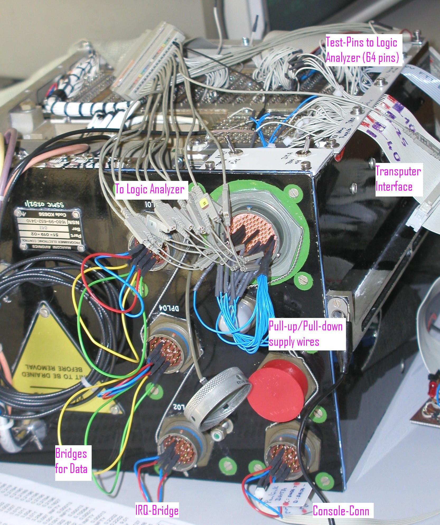
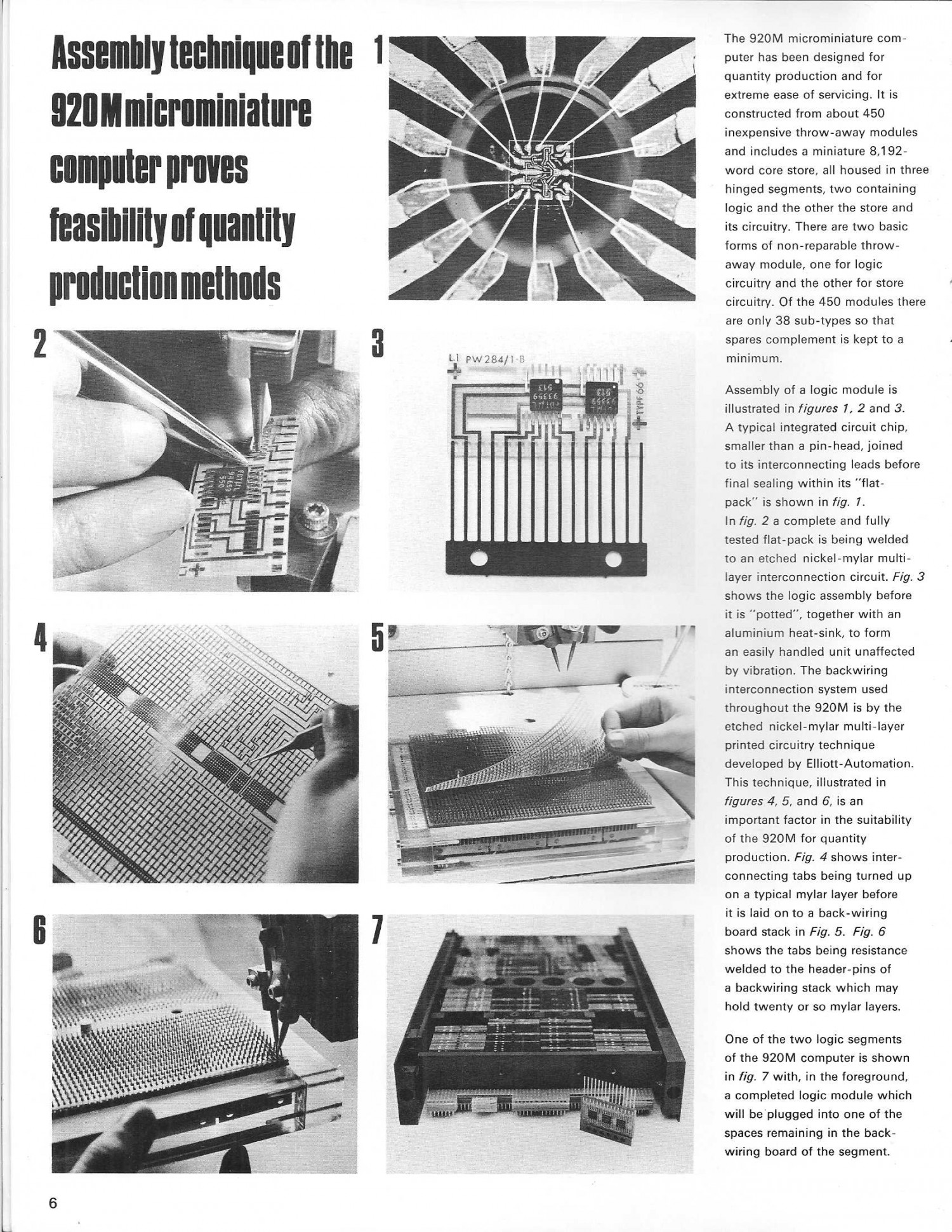
Two pages of an 1960ties brochure show some details of the internals
and
the assembly procedures of the 920Ms:
1
2.
The core memory of the 920M is made
by Plessey, holds two bits per plane
making a total of nine core planes plus two
for the diode arrays. The whole
stack is mounted in a sealed compartment (remember -
920M was intended for
use in space flight):
Left: Bigger poster illustrating 920M's core; Middle:
Illustration of the first instruction of the boot loader (called initial
instructions) and
right the "facts card" aka programming manual.
One reason for these machines being rather slow is the fact that in this
archaic architecture,
some registers are held in core and not in flip-flops
of the logic module. Therefore
many instructions require lot of core accesses
to keep everything up to date (even the much later
920ME using the 2900
chip set copies these registers to CMOS RAM to ensure software
compatibility).
Meanwhile, my setup is much better and consists of a sonobuoy homing panel
from the venerable
Nimrod MR2 which I retrofitted with an Arduino to implement a paper tape station
and TTY input/output
for user-interaction, which also works for the 920ME to be described in
the next section:
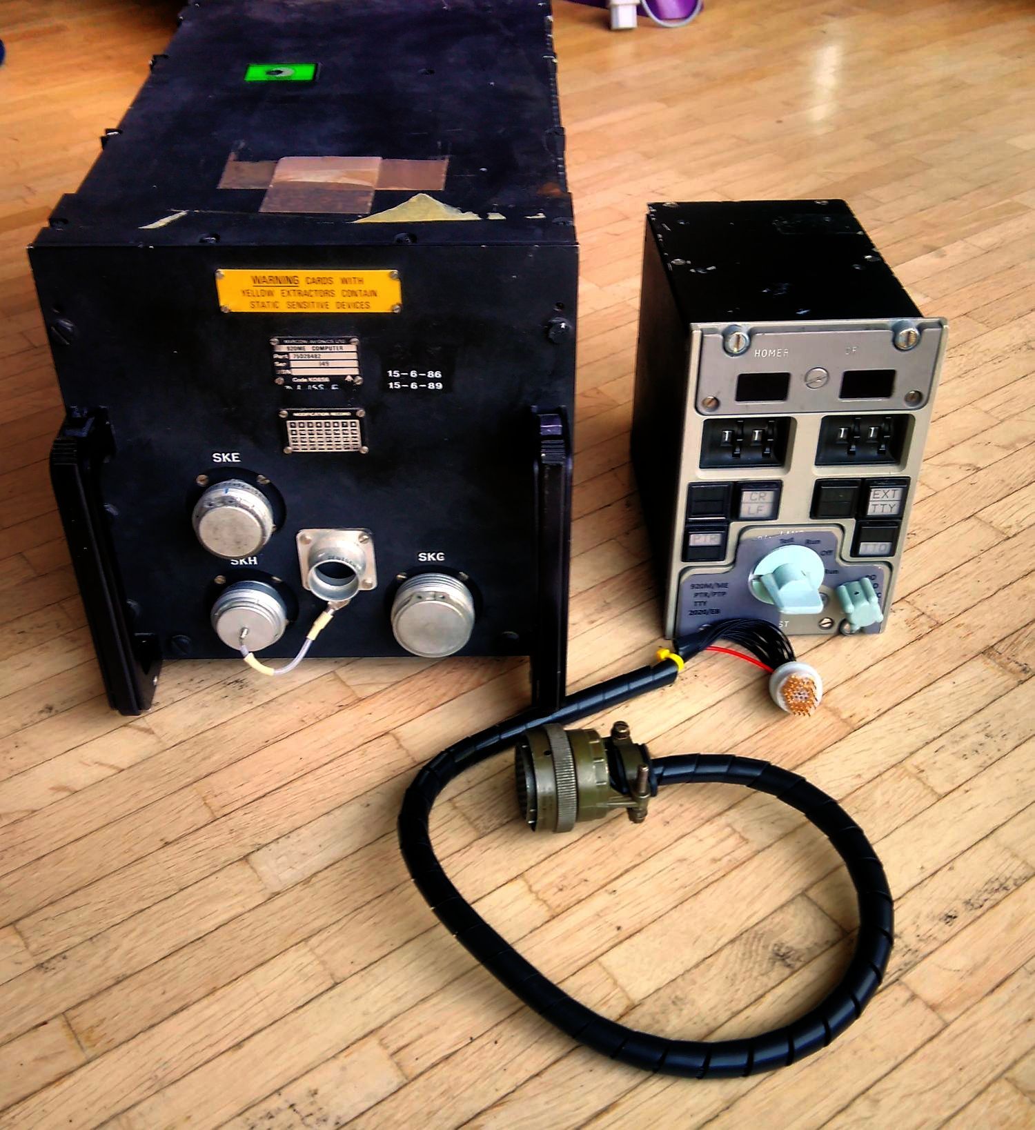
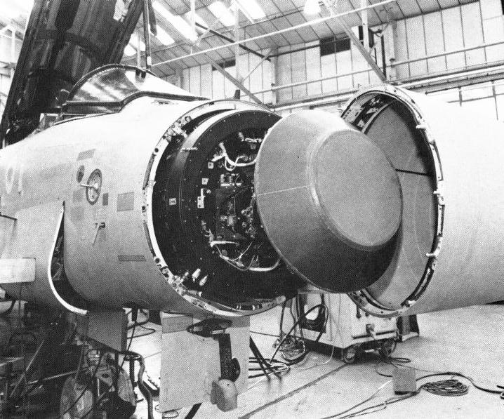
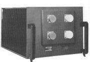
920ME (75D28482 - in use 1982-2014):
In 2016 I obtained a computer called 920ME from eBay - although quite expensive, the name forced me to buyit in hope to complete my collection by a 18 bit member of the Elliott 900 series:
![[920ME-eBay2.gif]](920ME-eBay2.gif)
![[920ME-ConditioningLabel.jpg]](920ME-ConditioningLabel.jpg)
The unit with part number 75D28482 contains several PCBs with DIL chips centered
around the AMD29xx minicomputer chipset.
The ALU is 18 bit wide and composed of five 2901s.
From the date codes the machine with serial number 140 must have been
manufactured
after mid of 1982:
To make it a replacement for the core memory based 920M they fitted CMOS ram (two
PCBs with 8k of store each) which is
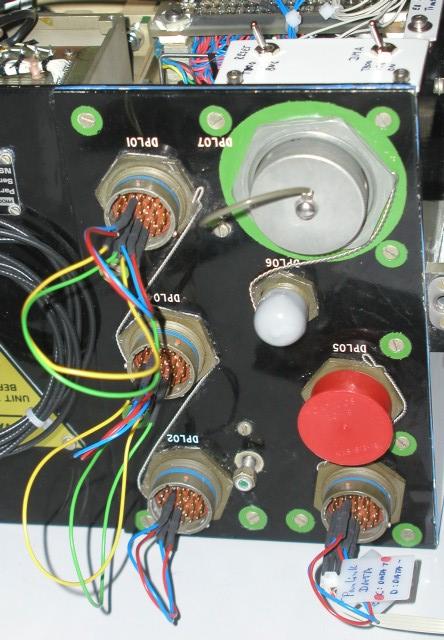
buffered by a battery. Two supplies deliver 5V
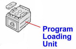
to logic and memory subsystem and the front side hosts three plugs. One for the
loading unit
and the two others probably for a panel (keys, start/stop etc.) and/or
memory expansion. Internally
an other two memory PCBs may be fitted giving a total
of 32k words of parity checked store:
![[920ME-Memory8k.JPG]](920ME-Memory8k.JPG)
Over 6 months I analyzed the plug for the loading unit and fixed some bugs (mainly a bunch of three
defective 54138 chips - all with same date code and a problem in the power supply). A homebrew interface
based on an Arduino MEGA is now interfacing the ME to a modern PC and it is emulating teletype and paper
tape stations. 9 paper tapes are hard-coded into the interface and a 10th can be loaded to the Arduino's RAM;
parity/telecode conversion can also be done by the new interface. As the plugs are very hard to find (RSM07 series),
the connection currently looks quite lousy but it works (any of the male
RSM07 plugs are welcome!):
![[920ME-LoadingConnector.JPG]](920ME-LoadingConnector.JPG)
![[920ME-RunningBASIC-SavageBenchmark.jpg]](920ME-RunningBASIC-SavageBenchmark.jpg)
After a visit of Terry in April 2017 where we ran tests he kindly prepared, we are now sure, that the
machine does not have the later additions to the command set implemented, so it does not obey the 905 or ATC
instructions, i.e. it especially does not have got floating point or stack operations in microcode. Apart
from this, there are some differences to the classic 920M instruction set in the 15 functions, but details
have to be analyzed: The 920ME is neither a 920M nor a 905 or ATC.
------------------------------------------------------------------
What makes the 920ME/M very interesting: There is way more software and documentation
available for the
18 bit machines than for the smaller 12 bit ones like 902/PEC. Andrew Herbert
collected nearly everything for the
900 series machines what survived the decades and his archive
is hosted by the Computer Conservation Society (CCS).
Among Algol, which is also part of my simulator in the next chapter, there are Fortran, BASIC and CORAL
out there.
As I final test for the ME I ran the
Savage
benchmark, I ran on the PEC in 2011, now on the "ME" using the
900 BASIC I obtained a license
from Terry. Here is a comparison of the accuracy of various test candidates...
...showing, that the floating point implementation within the 900 BASIC is much
better than the MECSL
floating point library available for the 12 bit
machines, but it is also slower as the 900 BASIC is optimized for extremely
little
memory usage and not for speed (It can be run in only 8k of store!). Together with the fact that the ME
is throttled to 920M speed
(or should I write "slowness"), the run time on "ME" is
comparable to the following "machines": HP-15C, Psion XPII or a HP-41CX.
8. Simulation for 12bit and 18bit Elliott machines

Software development for the 12-bit Elliott machines was often done on the bigger
18-bit machines (903, 920,...). For these Elliott 900 series of computers there
is a fascinating emulator initially written in 1983 by Terry Froggatt to run on VAX and
later on DOS using Meridian Ada. Afterwards it has been slightly modified and improved by
Don Hunter, who fixed a bug and added support for the plotter
and many examples for
the included Elliott Algol compiler. The DOS version (with and without plotter
support, source, manuals and with lot of examples) can be found on Don Hunter's page
as a SIM900AL zip-file.
Since I wanted to learn more on Ada, the Elliott 900 and since I love my SGI/IRIX boxes, I recently
ported this great emulator to gnat using GtkAda for the plotter emulation. This one runs on UNIX
operating systems (Sun, SGI) and on Windows 2000 or later. No Installation required!
Starting the emulator, the mission of Apollo8 around the moon is simulated. This
example for the Algol compiler must be from around 1964. The starting parameters of
the mission can be modified by editing the file ElliottIn.dat with an arbitrary text
editor. The first numbers on the last line in this file are starting height and speed.
Changing e.g. height from 300km to 305km you will observe a disaster happening at the end.
Keep in mind, that the Sim900al-NT runs many times faster on a decent PC or workstation
than on the original Elliott 903 or 920.
Download the latest version 1.3 of the emulator here, now containing all of
Don's Algol examples,
the source code and two utilities (one for converting paper
tapes from 903 telecode to ASCII and
another to view the headers of tapes -
thanks again to Terry):
| Architecture/OS | Version/Distri/HDD | Comment | Link |
|---|---|---|---|
| MIPS/IRIX | 1.3/3M5/12M7 | UNIX-Versions: Extract the tarball, cd to the generated directory and execute the bash script Sim900al-NT. This script will set the required environment variables and launch the architecture dependent binary afterwards. Read file readme.1st. | DOWNLOAD
|
| SPARC/Solaris | 1.3/5M8/19M0 | DOWNLOAD
|
|
| x86/Windows | 1.3/1M6/4M8 | Extract the zip file and directly start the Sim900al-NT.exe to launch the simulator. For more information read the file readme.1st.txt. | DOWNLOAD
|
Currently Peter Onion, who is working on the restoration of a 903 and who already wrote an
emulator for the 800 series Elliott computers (bit serial machines), is thinking about writing a new
simulator with fancy graphics and real-time behaviour for the linux platform. Visit his page here:
http://www.peteronion.org.uk/TNMOC-903/
Additionally there is a new 900 series emulator written recently in F# by Andrew Herb.
A very interesting fact is, that although there is no direct emulator for the 12 bit machines like PEC, these
machines can be
emulated as well: An emulator running on the 18 bit machines called SIM can be used to
run 12 bit code (including initial
instructions) on any 18 bit 900 series machine and especially within
my simulator. So to work with 12 bit Elliott code
on modern hardware, a two stage simulation works
very well; Compiling 12 bit software can also be done
using a single stage
simulation running the cross
assembler EHB directly within the 18 bit simulation.

![[p8172677.jpg]](p8172677.jpg)
![[TypePlate.jpg]](TypePlate.jpg)
![[Sticker1.jpg]](Sticker1.jpg)
![[Sticker2.jpg]](Sticker2.jpg)
![[Connectors.jpg]](Connectors.jpg)
![[ModuleRack.JPG]](ModuleRack.JPG)
![[Modules.JPG]](Modules.JPG)
![[BoxBottomWithOutSupply.jpg]](BoxBottomWithOutSupply.jpg)
![[CorePlaneLeft.jpg]](CorePlaneLeft.jpg)
![[CorePlaneRight.jpg]](CorePlaneRight.jpg)
![[DiodeArraysAndCore.jpg]](DiodeArraysAndCore.jpg)
![[MemDriverBrd.JPG]](MemDriverBrd.JPG)
![[CoreMemoryEarlyDoku.jpg]](CoreMemoryEarlyDoku.jpg)
![[ProcessorTiming.JPG]](ProcessorTiming.JPG)
![[PowerSuppSubAssy1.jpg]](PowerSuppSubAssy1.jpg)
![[PowerSuppSubAssy2.jpg]](PowerSuppSubAssy2.jpg)
![[SupplyBackplane.jpg]](SupplyBackplane.jpg)
![[SupplyWithSubAssembly.jpg]](SupplyWithSubAssembly.jpg)
![[Screws.jpg]](Screws.jpg)
![[Switches.jpg]](Switches.jpg)
![[DeviceUnderTest.jpg]](DeviceUnderTest.jpg)
![[CoreMemory.jpg]](CoreMemory.jpg)
![[PROMsFunctionDecode.jpg]](PROMsFunctionDecode.jpg)
![[TornadoLanding.jpg]](TornadoLanding.jpg)
![[TornadoComputerUnitSK10.gif]](TornadoComputerUnitSK10.gif)
![[TrapuInterface.jpg]](TrapuInterface.jpg)
![[CoreConnectConsole.jpg]](CoreConnectConsole.jpg)
![[Connection.jpg]](Connection.jpg)
![[T805RefreshProblem.jpg]](T805RefreshProblem.jpg)
![[RefreshDetect.jpg]](RefreshDetect.jpg)
![[T805RefreshProblemSolved.jpg]](T805RefreshProblemSolved.jpg)
![[T805refreshOK.jpg]](T805refreshOK.jpg)
![[ConsoleLCDonDPL03.jpg]](ConsoleLCDonDPL03.jpg)
![[Ferrit.jpg]](Ferrit.jpg)
![[PEC_SingleWrite.jpg]](PEC_SingleWrite.jpg)
![[PanLink1.gif]](PanLink1.gif)
![[PanLink2.gif]](PanLink2.gif)
![[SetUpPanorama.jpg]](SetUpPanorama.jpg)
![[SetUpPanoramaExplained.jpg]](SetUpPanoramaExplained.jpg)
![[920B_Function12_AP112H-0301.gif]](920B_Function12_AP112H-0301.gif)
![[_SecondUnit.jpg]](_SecondUnit.jpg)
![[_SecondUnitTypePlate.jpg]](_SecondUnitTypePlate.jpg)
![[_View1.jpg]](_View1.jpg)
![[_View2.jpg]](_View2.jpg)
![[_View3.jpg]](_View3.jpg)
![[_SecondUnitUnpacked.jpg]](_SecondUnitUnpacked.jpg)
![[_BackplaneView.jpg]](_BackplaneView.jpg)
![[_CageEmpty.jpg]](_CageEmpty.jpg)
![[_ConditioningLabel.jpg]](_ConditioningLabel.jpg)
![[_CoolantConnector.jpg]](_CoolantConnector.jpg)
![[_DifferenceBetweenUnits.jpg]](_DifferenceBetweenUnits.jpg)
![[_ModulesPulled.jpg]](_ModulesPulled.jpg)
![[PEC_TrapuIO20081022.JPG]](PEC_TrapuIO20081022.JPG)
![[CPLD-EvalPCBonPEC.jpg]](CPLD-EvalPCBonPEC.jpg)
![[Rotary100Winverter.jpg]](Rotary100Winverter.jpg)
![[PECversuchInverter20090214a.JPG]](PECversuchInverter20090214a.JPG)
![[SolderedPinsPain.jpg]](SolderedPinsPain.jpg)
![[InsertionRemovalTools-20090306.jpg]](InsertionRemovalTools-20090306.jpg)
![[DMCcrimper20090311a.jpg]](DMCcrimper20090311a.jpg)
![[EmptyPCBs.jpg]](EmptyPCBs.jpg)
![[FastLink-PCB.jpg]](FastLink-PCB.jpg)
![[FastLinkPCB-20090311.jpg]](FastLinkPCB-20090311.jpg)
![[TrapuLinkPCB-20090310.jpg]](TrapuLinkPCB-20090310.jpg)
![[DPL07experiment.jpg]](DPL07experiment.jpg)
![[PlotterSetup.jpg]](PlotterSetup.jpg)
![[PlotterPECTOS.jpg]](PlotterPECTOS.jpg)
![[PlotterOutput.jpg]](PlotterOutput.jpg)
![[Plotter-HPGL.jpg]](Plotter-HPGL.jpg)
![[DPL07-Cable-1.jpg]](DPL07-Cable-1.jpg)
![[DPL07-Cable-2.jpg]](DPL07-Cable-2.jpg)
![[DPL07-Cable-3.jpg]](DPL07-Cable-3.jpg)
![[Facit-N4000-PaperTape.jpg]](Facit-N4000-PaperTape.jpg)
![[Elliott-SAP.jpg]](Elliott-SAP.jpg)
![[WaveformGenerator-51-011-21.jpg]](WaveformGenerator-51-011-21.jpg)
![[WaveformGenerator-51-011-21-TypePlate.jpg]](WaveformGenerator-51-011-21-TypePlate.jpg)
![[PEC-LED-Line.jpg]](PEC-LED-Line.jpg)
![[PEC-LED-Line-Jig.jpg]](PEC-LED-Line-Jig.jpg)
![[DataMonitoringUnit-Parts.jpg]](DataMonitoringUnit-Parts.jpg)
![[3phaseInverter-2010326.jpg]](3phaseInverter-2010326.jpg)
![[3phaseInverter-2010325.jpg]](3phaseInverter-2010325.jpg)
![[Elliott905-Bletchley.jpg]](Elliott905-Bletchley.jpg)
![[TSR2-Cosford.jpg]](TSR2-Cosford.jpg)
![[PEC-SetupExplained-20100518.jpg]](PEC-SetupExplained-20100518.jpg)
![[SAP-on-PEC-20101108.gif]](SAP-on-PEC-20101108.gif)
![[WFG-TestPattern2.jpg]](WFG-TestPattern2.jpg)
![[WFG-MonitorMOD.jpg]](WFG-MonitorMOD.jpg)
![[PEC-Panel.gif]](PEC-Panel.gif)
![[PEC-BlinkenLights.jpg]](PEC-BlinkenLights.jpg)
![[PEC-BlinkenLightsExplained.jpg]](PEC-BlinkenLightsExplained.jpg)
![[BlinkenAction.jpg]](BlinkenAction.jpg)
![[PEC-OMP-Panel.jpg]](PEC-OMP-Panel.jpg)
![[PEC-OMP-Milling.jpg]](PEC-OMP-Milling.jpg)
![[PEC-OMP-View.jpg]](PEC-OMP-View.jpg)
![[MECSL-FloatTest-Multiply-12-2.gif]](MECSL-FloatTest-Multiply-12-2.gif)
![[MECSL-FloatTest-Divide-13-2.gif]](MECSL-FloatTest-Divide-13-2.gif)
![[MECSL-FloatTest-QFMATH-Exp.gif]](MECSL-FloatTest-QFMATH-Exp.gif)
![[MECSL-FloatTest-QFMATH-Sqrt.gif]](MECSL-FloatTest-QFMATH-Sqrt.gif)
![[MECSL-FloatTest-QFMATH-ATan-2.gif]](MECSL-FloatTest-QFMATH-ATan-2.gif)
![[MECSL-FloatTest-QFMATH-Sin-2.gif]](MECSL-FloatTest-QFMATH-Sin-2.gif)
![[MECSL-FloatSavage.gif]](MECSL-FloatSavage.gif)
![[MECSL-FloatTest-QFMATH-Ln-1.gif]](MECSL-FloatTest-QFMATH-Ln-1.gif)
![[MECSL-FloatTest-QFMATH-Ln-2.gif]](MECSL-FloatTest-QFMATH-Ln-2.gif)
![[MathSavage05.gif]](MathSavage05.gif)
![[MathSavage13.gif]](MathSavage13.gif)
![[MathSavage60.gif]](MathSavage60.gif)
![[MathSavage200Iterations.gif]](MathSavage200Iterations.gif)
![[PEC-OMP-Guts.jpg]](PEC-OMP-Guts.jpg)
![[PEC-OMP-1stTest.jpg]](PEC-OMP-1stTest.jpg)
![[WFG-Abgriffe.jpg]](WFG-Abgriffe.jpg)
![[WFG-Datagram-Setup.jpg]](WFG-Datagram-Setup.jpg)
![[WFG-RandomDatagram.jpg]](WFG-RandomDatagram.jpg)
![[TV-Tab-1.jpg]](TV-Tab-1.jpg)
![[PEC-OMP-1.jpg]](PEC-OMP-1.jpg)
![[PEC-OMP-2.jpg]](PEC-OMP-2.jpg)
![[PEC-OMP-Inverter1.jpg]](PEC-OMP-Inverter1.jpg)
![[PEC-OMP-Inverter2.jpg]](PEC-OMP-Inverter2.jpg)
![[PEC-OMP-Test.jpg]](PEC-OMP-Test.jpg)
![[TestWFG-SimonGreen-20130408.JPG]](TestWFG-SimonGreen-20130408.JPG)
![[PEC-OMP-Assembly0.JPG]](PEC-OMP-Assembly0.JPG)
![[PEC-OMP-Assembly1.JPG]](PEC-OMP-Assembly1.JPG)
![[PEC-OMP-Full.JPG]](PEC-OMP-Full.JPG)
![[PEC-OMP-Open.JPG]](PEC-OMP-Open.JPG)
![[PEC-OMP-Panel.JPG]](PEC-OMP-Panel.JPG)
![[PEC-OMP-Speaker.JPG]](PEC-OMP-Speaker.JPG)
![[AECM-Panel-Gr.1-Marked.jpg]](AECM-Panel-Gr.1-Marked.jpg)
![[AECM-Panel-Gr.1.jpg]](AECM-Panel-Gr.1.jpg)
![[TornadoCockpit-AECM-Marked.png]](TornadoCockpit-AECM-Marked.png)
![[AECM-Panel-Marked2.jpg]](AECM-Panel-Marked2.jpg)
![[AECM-Panel2.jpg]](AECM-Panel2.jpg)
![[AECM-Guts.jpg]](AECM-Guts.jpg)
![[AECM-Spy.jpg]](AECM-Spy.jpg)
![[NCS1-DCU-2.JPG]](NCS1-DCU-2.JPG)
![[NCS1-DCU-3.JPG]](NCS1-DCU-3.JPG)
![[NCS1-Unit-TimingPCB.jpg]](NCS1-Unit-TimingPCB.jpg)
![[TornadoUnit-Timing.jpg]](TornadoUnit-Timing.jpg)
![[AECM-Connected.jpg]](AECM-Connected.jpg)
![[AECM-Connected2.jpg]](AECM-Connected2.jpg)
![[AECM-LampTest.jpg]](AECM-LampTest.jpg)
![[PEC-Setup201404.JPG]](PEC-Setup201404.JPG)
![[Inverter1500-Testing.jpg]](Inverter1500-Testing.jpg)
![[Inverter1500-TopView.jpg]](Inverter1500-TopView.jpg)
![[TVtab-Test20141015.jpg]](TVtab-Test20141015.jpg)
![[Inverter1500-Housing1.jpg]](Inverter1500-Housing1.jpg)
![[Inverter1500-Housing2.jpg]](Inverter1500-Housing2.jpg)
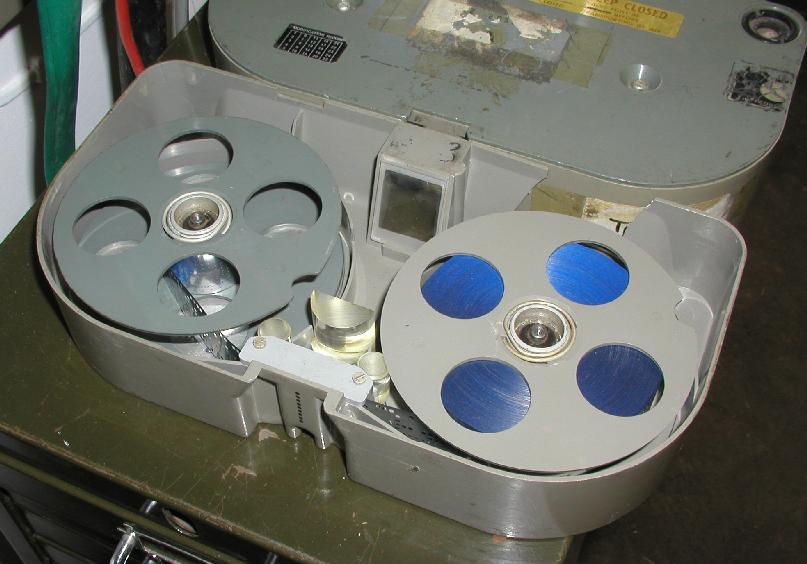
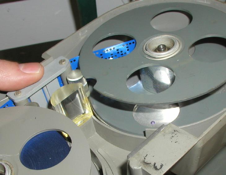
![[Leigh2.jpg]](Leigh2.jpg)
![[LeighCVR.jpg]](LeighCVR.jpg)
![[LeighLaufwerk.jpg]](LeighLaufwerk.jpg)
![[LeighMotors-Ritzel.JPG]](LeighMotors-Ritzel.JPG)
![[LeighRitzelvergleich.JPG]](LeighRitzelvergleich.JPG)
![[Leigh-VCRwithTape.JPG]](Leigh-VCRwithTape.JPG)
![[MotorPutt.JPG]](MotorPutt.JPG)
![[RitzelPutt.JPG]](RitzelPutt.JPG)
![[pics/903-PCB.gif]](pics/903-PCB.gif)
![[pics/903.jpg]](pics/903.jpg)
![[pics/905.jpg]](pics/905.jpg)
![[CambridgeWithTerry2015.JPG]](CambridgeWithTerry2015.JPG)
![[HMS-Belfast-ElliottMechComuter2015.JPG]](HMS-Belfast-ElliottMechComuter2015.JPG)
![[HMS-Belfast-GyroCompass2015.JPG]](HMS-Belfast-GyroCompass2015.JPG)
![[OxfordBigHall-2015.JPG]](OxfordBigHall-2015.JPG)
![[OxfordLevelyLandscape2015.JPG]](OxfordLevelyLandscape2015.JPG)
![[Terrys903panel-2015.JPG]](Terrys903panel-2015.JPG)
![[920ME-eBay1.jpg]](920ME-eBay1.jpg)
![[920ME-Interface-FrontPanelArduino.jpg]](920ME-Interface-FrontPanelArduino.jpg)
![[920ME-Interface-HomingWreck.jpg]](920ME-Interface-HomingWreck.jpg)
![[920ME-Interface-InterfaceCPLD.jpg]](920ME-Interface-InterfaceCPLD.jpg)
![[920ME-Interface-NewPCB.jpg]](920ME-Interface-NewPCB.jpg)
![[920ME-InterfaceTest.jpg]](920ME-InterfaceTest.jpg)
![[UK2019-Gifta.jpg]](UK2019-Gifta.jpg)
![[UK2019-IOMradar.jpg]](UK2019-IOMradar.jpg)
![[UK2019-NimrodNav.jpg]](UK2019-NimrodNav.jpg)
![[UK2019-RoyalAeroSpaceLib.jpg]](UK2019-RoyalAeroSpaceLib.jpg)
![[UK2019-StoneCircle.jpg]](UK2019-StoneCircle.jpg)
![[UK2019-TheDuke.jpg]](UK2019-TheDuke.jpg)
![[UK2019-TheDukeOps.jpg]](UK2019-TheDukeOps.jpg)
![[920MEplug-Extracted.jpg]](920MEplug-Extracted.jpg)
![[920MEplug-WrongOrientation.jpg]](920MEplug-WrongOrientation.jpg)
![[920M-MCM7-2.jpg]](920M-MCM7-2.jpg)
![[920M-MCM7-3.jpg]](920M-MCM7-3.jpg)
![[920MEfrontpanel.jpg]](920MEfrontpanel.jpg)
![[920MEtypelabel.jpg]](920MEtypelabel.jpg)
![[MCS920-Collection.JPG]](MCS920-Collection.JPG)
![[920PlugInsertGrinding.jpg]](920PlugInsertGrinding.jpg)
![[920PlugInsertLathe.jpg]](920PlugInsertLathe.jpg)
![[920PlugInsertMilled.jpg]](920PlugInsertMilled.jpg)
![[920PlugInsertsRaw.JPG]](920PlugInsertsRaw.JPG)
![[920PlugMilling.JPG]](920PlugMilling.JPG)
![[920MInsertsSortiment.jpg]](920MInsertsSortiment.jpg)
![[920MpowerPlugB.jpg]](920MpowerPlugB.jpg)
![[920MpowerSetup.jpg]](920MpowerSetup.jpg)
![[StoreModule.gif]](StoreModule.gif)