Vintage Computing / Avionics and
"Programmer Electronic Control"
- Chronology and log-book -
Part No. 51-019-02, NSN 1680-99-652-3410,
Supplier K0656, Marconi Avionics, UK
- and many others -
Everything started in 2004 with obtaining PEC...
...leading to an exciting hobby of reverse-engineering, understanding
various avionics stuff from the 1970ties and bringing lot of the cool
technology back to working condition again...
2004 |
2004 |
2004 | ||||||||||||||||||||||||||||||||||||||||||||||||||||||||||||||||||
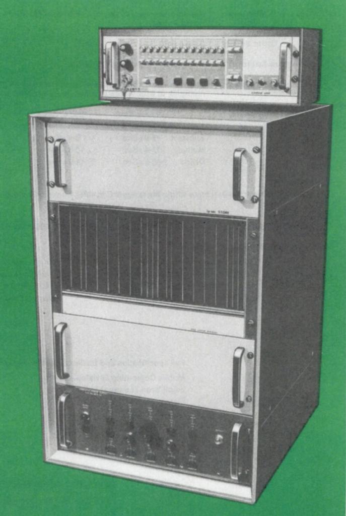
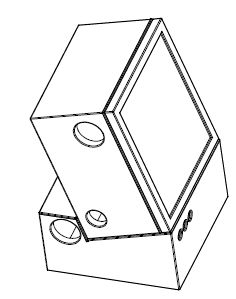
| 11/29/2004 | Got PEC serial 42 from Abex Co./UK (eBay). | Serial 42![[p8172677.jpg]](p8172677.jpg) ![[TypePlate.jpg]](TypePlate.jpg) | ||||||||||||||||||||||||||||||||||||||||||||||||||||||||||||||||||
| 12/16/2004 | Made inventory of NSNs of the installed PCBs and submitted first posting. Found
out, that timing is generated by mono-flops of type 74121 and made first list of chips
used. Submitted posting on the unit with several questions in the use-net group rec.aviation.military. |
 | ||||||||||||||||||||||||||||||||||||||||||||||||||||||||||||||||||
2005 |
2005 |
2005 | ||||||||||||||||||||||||||||||||||||||||||||||||||||||||||||||||||
| 1/10/2005 | Deciphered pin-out of the 8 PROMs used on the SK11, "Function Decode PCB" for the microcode of the unit. They are compatible to the 82S123 being 32bytes with open collector output. | 82S123 data-sheet | ||||||||||||||||||||||||||||||||||||||||||||||||||||||||||||||||||
| 2/19/2005 | Analyzed the output section of the power supply: Supply voltages of the unit are clear now as well as a "power good" signal. There is some kind of feedback from the unit (later it became evident, that the core voltage and thus the currents are adjusted according to the temperature of the core-plane). Still unclear: What is the input voltage (guess 115VAC, 3phase) and how to supply/generate this. | ![[PowerSuppSubAssy1.jpg]](PowerSuppSubAssy1.jpg) |
||||||||||||||||||||||||||||||||||||||||||||||||||||||||||||||||||
| 2/22/2005 | Layout and principle of operation of the core section roughly analyzed. Sketch of the schematic completed: Memory is 12bit*8192 words. | ![[CoreMemory.jpg]](CoreMemory.jpg) ![[DiodeArraysAndCore.jpg]](DiodeArraysAndCore.jpg) |
||||||||||||||||||||||||||||||||||||||||||||||||||||||||||||||||||
| 2/25/2005 | Submitted posting to the "Professional Pilots Rumor Network" (PPRuNe) to see whether there is someone out there recognizing the unit and having any information. Unfortunately there was no feedback. |  | ||||||||||||||||||||||||||||||||||||||||||||||||||||||||||||||||||
| 3/12/2005 | Rx-Tx-Board investigated: Contains 100R differential line drivers. Four links are highly symmetric and can only be used one-at-a-time. Rough sketch of this section complete. | 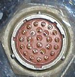 | ||||||||||||||||||||||||||||||||||||||||||||||||||||||||||||||||||
| 3/29/2005 | Checked SK10, the "Control Register" and drew rough schematic diagram. Decision: unit must be complete Computer and is worth further investigation. Connected logic analyzer (Agilent 1661A) to the pins known up to now and prepared power supplies for external input. Removed core plane and stored at save location (idea: might still contain code which can be recovered later to learn about the command set). | ![[TornadoComputerUnitSK10.gif]](TornadoComputerUnitSK10.gif) | ||||||||||||||||||||||||||||||||||||||||||||||||||||||||||||||||||
| 4/11/2005 | After trouble with the logic analyzer's floppy, setup now via GPIB control from Sun SPARC Station 20 which works great. Started investigation of the signals at the memory and memory-processor-interface. Connected DIP switch to apply defined bit pattern to be read from non-existent core plane. Discovered a GOTO-like command (later RJMP). | ![[Switches.jpg]](Switches.jpg) | ||||||||||||||||||||||||||||||||||||||||||||||||||||||||||||||||||
| 8/11/2005 | SK8 and SK9 analyzed: They contain accumulator and ALU (some adder, shifter
etc.) and each of the identical PCBs holds 6 bits. First computer generated
diagrams of PEC's internals complete for documentation
purposes. From the already known commands, idea emerged to write an assembler in TCL and implement discovered commands simultaneously. This proved extremely valuable later as platform for writing test programs to investigate and analyze further commands... |
"Birth" of Assembler: pecasm V0.1  | ||||||||||||||||||||||||||||||||||||||||||||||||||||||||||||||||||
| 8/20/2005 | Next level in the analysis-setup: Built hand-wired interface between a Parsytec-Megaframe Transputer PCB and the PEC. This allows to apply bit patterns to the PEC's bus. Connected this to the unit with the logic analyzer. Transputer and logic analyzer are controlled via workstation (Sun SparcStation20, dual Ross-200) allowing rapid cycles of applying patterns and analyzing them. | ![[Connection.jpg]](Connection.jpg) ![[TrapuInterface.jpg]](TrapuInterface.jpg) | ||||||||||||||||||||||||||||||||||||||||||||||||||||||||||||||||||
| 10/10/2005 | Setup now able to generate timing for accessing core memory. Inserted the core module again and verified correct behavior on word 0 of the memory. After adjustments of voltages and timing read out the whole memory 5 times. Got 5 nearly identical copies (error rate about 1 wrong bit per 4000, reason unknown by 2005). But memory did not contain any useful information: Mainly 0 and only very few 1s -> No usable information in core memory found! | Hex-File | ||||||||||||||||||||||||||||||||||||||||||||||||||||||||||||||||||
| 10/11/2005 | Additional information: PEC starts operation at 0xa0 after reset. Setup now able to write core, observe 100us of operation of PEC via the logic analyzer and read out memory afterwards. Basically, this setup remained unchanged for a very long time. | ![[SetUpPanoramaExplained.jpg]](SetUpPanoramaExplained.jpg) | ||||||||||||||||||||||||||||||||||||||||||||||||||||||||||||||||||
| 25/11/2005 | Reverse engineered timing generator for core memory. Made documentation of read/write timing. | ![[PEC_SingleWrite.jpg]](PEC_SingleWrite.jpg) | ||||||||||||||||||||||||||||||||||||||||||||||||||||||||||||||||||
| 12/01/2005 | After many postings in rec.aviation.military regarding PEC, this tread leads to suspicion that PEC controlled navigator's displays in Panavia Tornado. | ![[TornadoLanding.jpg]](.catalogimages/TornadoLanding-jpg-indexicon.jpg) | ||||||||||||||||||||||||||||||||||||||||||||||||||||||||||||||||||
| 05/12/2005 | Measurements on patch-panel and connected more of the relevant signals (SK7 and SK15 mainly) to the logic analyzer. | ![[DeviceUnderTest.jpg]](DeviceUnderTest.jpg) | ||||||||||||||||||||||||||||||||||||||||||||||||||||||||||||||||||
2006 |
2006 |
2006 | ||||||||||||||||||||||||||||||||||||||||||||||||||||||||||||||||||
| 02/09/2006 | Discovered, that freezing of PEC is related to bit 7 in instructions like STA and is related to IDX register, too. Commands confirmed: ADD (no carry!), LDI, STA. Assembler extended to accept the new commands. | ADD, LDI, STA Assembler V0.96 | ||||||||||||||||||||||||||||||||||||||||||||||||||||||||||||||||||
| 03/20/2006 | Instructions SHR and SHL analyzed, added to the assembler. Current version 0.97. | SHR, SHL Assembler V0.97 | ||||||||||||||||||||||||||||||||||||||||||||||||||||||||||||||||||
| 04/22/2006 | Conditional jumps RJAZ and RJAN discovered: Jump if accumulator holds zero or is negative. Assembler extended to accept these commands and produce various list files (hex, octal). Version is 0.98 now. Interesting notice: This machine does not have a carry bit, thus writing e.g. 24bit arithmetics is not that easy. | RJAN, RJAZ pecasm V0.98 | ||||||||||||||||||||||||||||||||||||||||||||||||||||||||||||||||||
| 05/28/2006 | Deciphered input and output format on the fast links DPL1 to DPL4; sketches of the associated circuits complete: Transmission is SPI-like with 3bit header, R/W bit followed by 12 bits of data. End of transmission is indicated by dropping one clock cycle. | ![[PanLink2.gif]](PanLink2.gif) | ||||||||||||||||||||||||||||||||||||||||||||||||||||||||||||||||||
| 11/22/2006 | Discovered that occasional memory errors in writing to core by the Transputer are related to the T805's refresh cycles. Fixed this problem by a small additional PCB on the Transputer interface detecting refresh
cycles which can thus be avoided to interfere with the code writing to core. During this experiment also made measurements on the temperature dependency of optimum currents to operate the core stack. |
![[T805refreshOK.jpg]](T805refreshOK.jpg) | ||||||||||||||||||||||||||||||||||||||||||||||||||||||||||||||||||
| 12/08/2006 | Plugs identified as MIL38999 plugs. Sorted out Amphenol part numbers and ordered socket contacts for tests at GlenAir/Germany. | ![[Connectors.jpg]](Connectors.jpg) | ||||||||||||||||||||||||||||||||||||||||||||||||||||||||||||||||||
2007 |
2007 |
2007 | ||||||||||||||||||||||||||||||||||||||||||||||||||||||||||||||||||
| 01/07/2007 | Discovered UMUL and confirmed as unsigned MUL. But by this time, I had not fully understood that the extension register holding the additional 12 bits
of the result is the same as the index register B. Roger Holmes gave me the right hint later this year - Thanks! Up to now, the large setup with it's many switch mode power supplies caused spikes in measurements with the oscilloscope due to grounding problems. Added ferrite cores to reduce common mode noise making measurements much easier. Oscilloscope can now be triggered by the logic analyzer. |
UMUL Multiplication![[Ferrit.jpg]](Ferrit.jpg) | ||||||||||||||||||||||||||||||||||||||||||||||||||||||||||||||||||
| 01/14/2007 | Hand-wired console LCD completed. This connects to one of the fast serial links of the unit and is powered by a 9V battery. Works fine and first "Hello World" program executed successfully on PEC. | ![[ConsoleLCDonDPL03.jpg]](ConsoleLCDonDPL03.jpg) | ||||||||||||||||||||||||||||||||||||||||||||||||||||||||||||||||||
| 2/25/2007 | Assembler: Improved handling of labels, implemented support for macros using the M4 macro processor. Added all commands deciphered up to now with parameter checking and error messages. Version increased to 0.99. | Assembler pecasm V0.99 | ||||||||||||||||||||||||||||||||||||||||||||||||||||||||||||||||||
| 03/08/2007 | Posting in classiccmp mailing list with short report on my efforts. In the emerging thread, the command set is being identified as being similar to the Elliott900 series computer (Hint from Roger Holmes: Elliott 900 uses 18bits and a very similar structure of commands!). Before submitting the initial posting, I put a description of the commands known up to date online into my home-page. | Somewhat later and extended pdf version of the original posting:  | ||||||||||||||||||||||||||||||||||||||||||||||||||||||||||||||||||
| 03/17/2007 | Confirmed addressing mode "modified" to be M*D*128+offset. This causes PEC to freeze (even reset can not clear this lock), if an address outside of PEC's memory is being accessed. During search for yet undiscovered commands, came across some kind of RETFI (return from interrupt) instruction. | Indirect Addressing RETFI | ||||||||||||||||||||||||||||||||||||||||||||||||||||||||||||||||||
| 03/18/2007 | Released second, strongly expanded, version of my documentation on the Programmer Electronic Control via the project's web page. This contains a description of most commands deciphered so far with execution times. In the appendix there some sketches on PEC's internals and timing diagrams as well. |  | ||||||||||||||||||||||||||||||||||||||||||||||||||||||||||||||||||
| 03/21/2007 | Discovered that there are several interrupt vectors which are accessed in entering interrupt level. But only one return address associated to the RETFI instruction. This was the start of investigation of the interrupts and IO machinery. In total this was much more difficult than anticipated and consumed nearly the same time the whole process up to now did! | IRQs discovered | ||||||||||||||||||||||||||||||||||||||||||||||||||||||||||||||||||
| 04/15/2007 | Got a Ferranti FIN1010 inertial navigation system via Helmut Singer. Bought this because
I had the idea that this could be connected to PEC. Investigated the included computer,
but technology is different and there is no way that this was connected to PEC. But nevertheless, the Internet store of Helmut-Singer always offers strange and interesting items. |
Helmut Singer GmbH | ||||||||||||||||||||||||||||||||||||||||||||||||||||||||||||||||||
| 08/12/2007 | Submitted posting to the German avionics/aircraft group on the FlugzeugForum, www.flugzeugforum.de. There emerged some interesting discussion on Tornado, it's computers and displays. But no hint on the Programmer Electronic Control or it's application. |  | ||||||||||||||||||||||||||||||||||||||||||||||||||||||||||||||||||
| 08/15/2007 | Second try in submitting a posting to the "Professional Pilots Rumor Network", www.pprune.org. This time, there was some feedback on the Tornadoes displays. But no input specifically regarding the Programmer Electronic Control. |  | ||||||||||||||||||||||||||||||||||||||||||||||||||||||||||||||||||
| 09/15/2007 | Got PEC serial 129, again from Abex Co./UK (direct sale). In comparing the two units, some differences regarding the grounding scheme became apparent. Apart from some obvious questionable design features of all units (e.g. the covers are electrically insulated from the housing by the black painting used - very strange) they obviously had special grounding problems at the plugs, leading to added grounding in unit No. 129. | Serial 129![[_DifferenceBetweenUnits.jpg]](_DifferenceBetweenUnits.jpg) | ||||||||||||||||||||||||||||||||||||||||||||||||||||||||||||||||||
| 10/27/2007 | Investigated slow link on DPL05. Format of 24 bit in/output is clear, but completely unclear remains how to sync software's read and write access to the shift registers with transmission itself. | - | ||||||||||||||||||||||||||||||||||||||||||||||||||||||||||||||||||
| 11/01/2007 | Released third, revised, version of my documentation on the Programmer Electronic Control. | | ||||||||||||||||||||||||||||||||||||||||||||||||||||||||||||||||||
| 11/16/2007 | Input from experts at "Deutsches Museum" that liquid cooling often is only present in radar systems and not in ordinary avionics applications. This new input ruled out the navigator's displays as application for the units. Since the original source of the units insisted that the units are from a Tornado application, a new hypothesis emerged: The units might have been used on the Foxhunter radar of the Tornado ADV. | The unit's coaxial connector for liquid cooling: ![[_CoolantConnector.jpg]](_CoolantConnector.jpg) New suspected application: 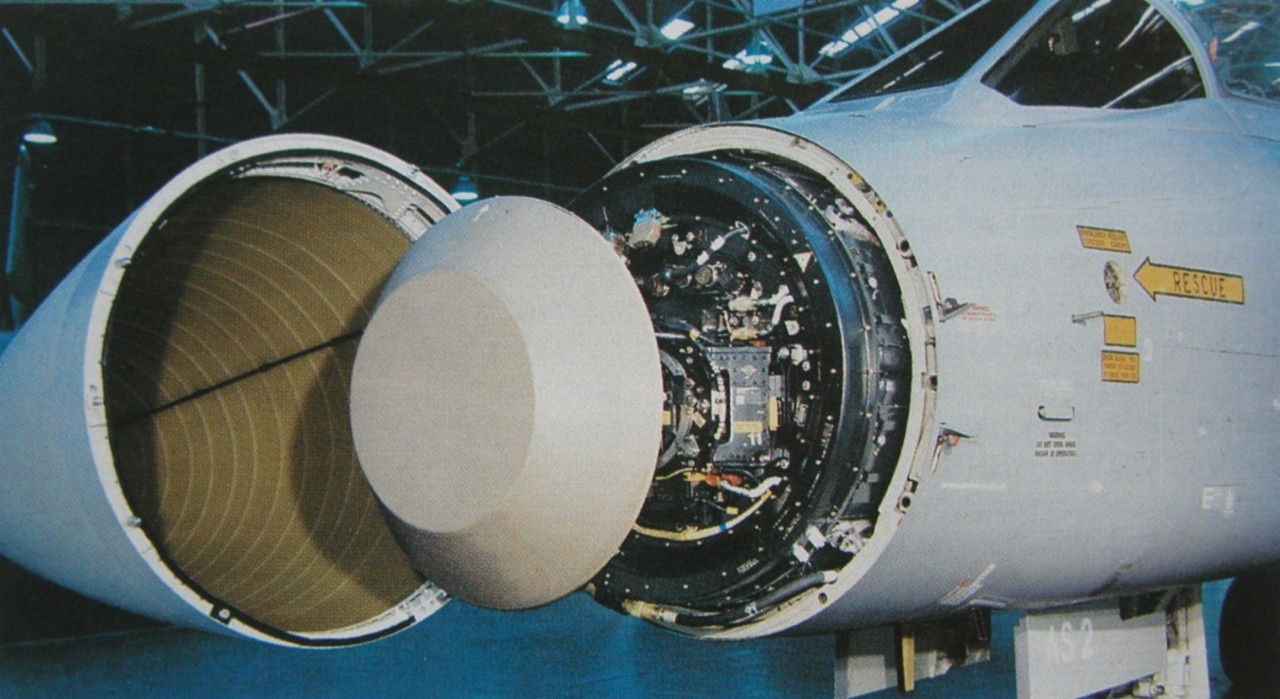 | ||||||||||||||||||||||||||||||||||||||||||||||||||||||||||||||||||
| 11/27/2007 | The continuously growing test program used for many different tasks got sufficiently versatile (e.g. includes display support) making it worth being called programmer electronic control - tiny operating system alias pec-tos. | PEC Operating System Birth of pec-tos, V0.60 | ||||||||||||||||||||||||||||||||||||||||||||||||||||||||||||||||||
| 12/17/2007 | Confirmation by Roger Holmes (who asked Terry Froggatt as I was told later) that the unit's architecture is indeed very similar to the Elliott computers and the unit might be an Elliott 12/12 airborne computer. |  | ||||||||||||||||||||||||||||||||||||||||||||||||||||||||||||||||||
2008 |
2008 |
2008 | ||||||||||||||||||||||||||||||||||||||||||||||||||||||||||||||||||
| 02/08/2008 | Got information, that liquid cooling in Tornado is only used in ADV's radar system utilizing Coolanol. Subsequently found traces of a red fluid in the ducts of PEC which matches the look of Coolanol. Therefor PEC finally ruled out being related to the cockpit displays in Tornado. New hypothesis is, that PEC was used in the first stages of the Foxhunter AI24 radar (Stage1, and Stage 1+) which was unable to fully meet the required specifications. According to the time line of Foxhunter development, the units (if really used in Foxhunter) where in service until 1996 when the digital electronics in Foxhunter was replaced to lead to Stage2 for this radar system. | Foxhunter article on the Internet. | ||||||||||||||||||||||||||||||||||||||||||||||||||||||||||||||||||
| 02/18/2008 | Got PEC serial 90 from Tim Wayre in UK via eBay. | Serial 90![[_View1.jpg]](_View1.jpg) | ||||||||||||||||||||||||||||||||||||||||||||||||||||||||||||||||||
| 04/29/2008 | Completed porting the sim900al emulator by Terry Froggatt and Don Hunter to gnat Ada by implementing new graphics handling - first release (Windows,
IRIX, Solaris). The emulation runs about 10 times faster than the original
machine on a 500MHz UltraBook. As of 2017, this is superseded by V1.3 - link updated! |
Sim900al-NT, V1.3 | ||||||||||||||||||||||||||||||||||||||||||||||||||||||||||||||||||
| 05/01/2008 | Investigated IRQ circuit, hereby identified the possible IRQ sources (0: Unknown,1: SlowLink,2: Timer,3: FastLink Rcv,4-7: DPL1-4) and the associated IRQ vectors. Timer IRQ is working already. IRQs of the fast links are always asserted if no device is connected. Applied bridges to turn them off. | IRQbridges on DPL01-DPL04 | ||||||||||||||||||||||||||||||||||||||||||||||||||||||||||||||||||
| 05/03/2008 | Released document showing detailed photographs of all PCBs of PEC, serial PEC129. Shown are component and solder side of each PCB on a separate page. | PCBs of PEC No.
129 | ||||||||||||||||||||||||||||||||||||||||||||||||||||||||||||||||||
 05/15/2008 05/16/2008  |
Joined the CCS seminar "Early computer programming at Elliotts" in London: Got more information
on the 920, 902 and 12/12 series of computers from Terry Froggatt. Especially fruitful was the
personal discussion with Terry on the following day together with the demonstration of his
just repaired 920. This was definitively one of the the most exciting
days in the PEC related
research. On 5/16/2008 I visited the RAF Museum near London. Apart from many interesting aircraft, they have a huge archive holding many air publications. Among them I found documents related to the Nimrod reconnaissance aircraft, which used the 18 bit Elliott 920M in various applications. One of these documents even contained flow charts of the microcode and complete schematics of the Elliott 920M unfortunately too many pages to make copies of... |
 902 Facts
Card
902 Facts
Card 12-12-Specification 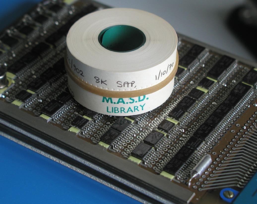
| ||||||||||||||||||||||||||||||||||||||||||||||||||||||||||||||||||
| 05/23/2008 | Deciphered in detail how the IRQack command works and sorted out what the bits in the IRQmask part of this instruction mean. Assembler support for these instructions added, documentation updated. | IRQack, pecasm V1.03. | ||||||||||||||||||||||||||||||||||||||||||||||||||||||||||||||||||
| 06/08/2008 | Added timer interrupt handling to pec-tos, converted all comments to English and performed severe clean up. Now the OS handles all interrupts in parallel and prints letters to the console for each IRQ call handled. All interrupts work nicely in parallel now! | pec-tos V0.70 | ||||||||||||||||||||||||||||||||||||||||||||||||||||||||||||||||||
| 06/17/2008 | Last custom chip reverse engineered by ohmic and dynamic measurements. All chips within PEC (even custom ones) identified now. Launched separate page listing all the chips with data-sheets and a statistics showing the date codes of the chips used in PEC #42. |  | ||||||||||||||||||||||||||||||||||||||||||||||||||||||||||||||||||
| 06/23/2008 | Discovered the blinkenlights-bus, a data-bus dedicated to debugging and hardware diagnosis leading to the big programming- and diagnosis-plug DPL07. Functions deciphered by 80 percent. First experiments of attaching a cable to the diagnosis plug DPL07 of PEC using an Amphenol plug with soldered socket contacts - inserting and removing such socket contacts is really pain and for final blinkenlights this has to be done by the properly crimped connections. | ![[SolderedPinsPain.jpg]](SolderedPinsPain.jpg) | ||||||||||||||||||||||||||||||||||||||||||||||||||||||||||||||||||
| 07/16/2008 | Remaining pins of DPL07 recognized and more than 90 percent known. List with function descriptions for documentation purposes generated (first version). | - | ||||||||||||||||||||||||||||||||||||||||||||||||||||||||||||||||||
| 09/10/2008 | Added a PROCEDURE mechanism to pec-tos using macros. This mechanism allows
comfortable definition and calling of functions and procedures where the assembler
is implementing everything (memory allocation for destination- and return addresses)
automatically using PEC's IDXCALL command. BTW: The Elliott machines (as many other machines of those days, e.g. PDP8 from Digital Equipment, too) do not have got a stack as modern computers do. Thus calling subroutines and sending parameters to them has to be handled in a different and rather complex way. |
pec-tos V0.80 | ||||||||||||||||||||||||||||||||||||||||||||||||||||||||||||||||||
| 10/25/2008 | All interrupts work reliably and in parallel now in PEC-TOS (aka PEC-Tiny/Trivial-Operating-System) V0.81. Major new discovery: Sync with SlowLink on DPL05 has to be done by it's associated interrupt: Immediately after the interrupt is asserted by the hardware, there is a window of about 100us time during which the 24 bit value received can be read from the shift registers and the value to be transmitted can be written. Despite the link being slow, this update of the shift registers is very important and thus this IRQ has a very high priority... | Slow Link pec-tos V0.81 | ||||||||||||||||||||||||||||||||||||||||||||||||||||||||||||||||||
| 12/17/2008 | Simulated memory expansion to 32k words via DPL07 and the Transputer setup successfully for the first time. External simulation of paper tape and TTY also successfully implemented in Transputer, too (all used only one out of 12 bits). Added commands RPPT, WPPT, RTTY and WTTY to assembler. | RTTY, WTTY, RPPT, WPPT![[PEC_TrapuIO20081022.JPG]](PEC_TrapuIO20081022.JPG)
| ||||||||||||||||||||||||||||||||||||||||||||||||||||||||||||||||||
2009 |
2009 |
2009 | ||||||||||||||||||||||||||||||||||||||||||||||||||||||||||||||||||
| 01/07/2009 | Ideas for building new console with display, switches and 8751 processor to interface a plotter finalized. As well as way to go to build blinkenlights and second generation of Transputer-interface to connect to DPL07 decided. Selected suitable programmable logic device and conducted first experiments using an evaluation board of this EPM7128 from Altera connected to PEC. Started PCB design using EAGLE5.3 -> 4-layer PCBs. | ![[CPLD-EvalPCBonPEC.jpg]](CPLD-EvalPCBonPEC.jpg) | ||||||||||||||||||||||||||||||||||||||||||||||||||||||||||||||||||
| 01/18/2009 | Frederic Im. from France connected me via email regarding the PEC. He acquired >10 of them and is currently reusing the outer case of a unit for a project with the vintage Intel 4004 processor. In the weeks to follow he reverse engineered the input section of PEC's power supply and managed to power up his units continuously. I have got no further information, what his plan about his units is. | - | ||||||||||||||||||||||||||||||||||||||||||||||||||||||||||||||||||
| 02/12/2009 | Got new PCBs from manufacturer: New Trapu-Link and new FastLink-interface. Started CPLD development and mounting of components. The new Transputer-interface was up and running within one day - now featuring a digital means of detecting the refresh cycles of the Transputer thus allowing faster and more reliable programming of PEC's core memory. This new interface will go in service together with the new blinkenlights - hopefully beginning of 2010... |
![[EmptyPCBs.jpg]](EmptyPCBs.jpg) | ||||||||||||||||||||||||||||||||||||||||||||||||||||||||||||||||||
| 03/20/2009 | PEC #129 runs on it's own supply in intermittent operation using a rotating inverter and a battery of transformers to step up from 115VAC to 200VAC 3 phase current. Power of the inverter (being from an Alouette helicopter) of 100W is not enough for continuous operation of PEC but nevertheless the inverter is a beautiful and very noisy device. Interesting issue: The inverter has only four pins: Negative input and one of the three phases are connected to chassis... ;-) | ![[PECversuchInverter20090214a.JPG]](PECversuchInverter20090214a.JPG)
![[Rotary100Winverter.jpg]](Rotary100Winverter.jpg) | ||||||||||||||||||||||||||||||||||||||||||||||||||||||||||||||||||
| 4/6/2009 | Got proper tools via eBay for making professional crimped connections of various cables to the AMP plug. Completed tests on which cabling to use in connecting the future blinkenlights- and Transputer-setup to DPL07 without hampering signal quality. PEC's cycle time is on the order of 1us, but timing is critical since the unit is asynchronous. Ringing etc. has to be kept to a minimum to ensure reliable operation. | ![[DMCcrimper20090311a.jpg]](DMCcrimper20090311a.jpg)
![[InsertionRemovalTools-20090306.jpg]](InsertionRemovalTools-20090306.jpg) | ||||||||||||||||||||||||||||||||||||||||||||||||||||||||||||||||||
| 04/10/2009 | Released newest version of my documentation on the Programmer Electronic Control - now rather complete with details on interrupts and corrected errors in the section on the fast links. Timing diagrams on fast link transmission (send and receive) are given in the appendix. | | ||||||||||||||||||||||||||||||||||||||||||||||||||||||||||||||||||
| 04/12/2009 | New FastLink-PCB working properly: Possible to write AND read via FastLinks DPL01-DPL04. Implemented console abstraction in pec-tos to switch easily between old hand-wired and new console PCBs. CPLD-Design complete, 8751 operational. The picture on the left shows PEC-TOS online. The letters in the second line show which switches on the console are on (K) and which interrupts occurred in the first 100ms of operation. | pec-tos V0.84![[PlotterPECTOS.jpg]](PlotterPECTOS.jpg) | ||||||||||||||||||||||||||||||||||||||||||||||||||||||||||||||||||
| 04/29/2009 | Removed minor bug in pec-tos with pointer handling and reworked the TRAP macro, allowing to stop the OS giving a message on the new console display. | pec-tos V0.85 | ||||||||||||||||||||||||||||||||||||||||||||||||||||||||||||||||||
| 06/06/2009 | Implementation of driver for pen plotter CalComp M84 in FastLink PCB completed; API included within the operating system to move and draw with relative and absolute coordinates and to send commands to the plotter. Essentially plotter commands from PECs view are single assembler
instructions: PlotterPreLoadX, 15/1/6, Preload new x position from accumulator. PlotterPreLoadY, 15/1/7, Preload new y position from accumulator. PlotterDrawX, 15/1/8, Draw using accumulator as x and preloaded y. PlotterDrawY, 15/1/9, Draw using accumulator as y and preloaded x. PlotterMoveX, 15/1/10, Move using accumulator as x and preloaded y. PlotterMoveY, 15/1/11, Move using accumulator as y and preloaded x. Digitized a picture of PEC via xfig, converted to hpgl and from there using a home-brew program to an asm-file for pecasm, containing the data. Now pec-tos can draw a simple geometric pattern, write text and draw an outline of PEC. Unfortunately there is some issue with certain core pages preventing to load the full data set to PEC. Thus only the plug-section of PEC's outline is drawn by the plotter. |
pec-tos V0.90![[Plotter-HPGL.jpg]](Plotter-HPGL.jpg)
![[PlotterOutput.jpg]](PlotterOutput.jpg) | ||||||||||||||||||||||||||||||||||||||||||||||||||||||||||||||||||
| 6/28/2009 | After hours of fiddling around with the insertion and removal tools, the cable connecting to the diagnosis and programming plug of PEC is completed and the plug assembled. Cable itself is made from Amphenol spectra strip ribbon cable. |
![[DPL07-Cable-2.jpg]](DPL07-Cable-2.jpg)
| ||||||||||||||||||||||||||||||||||||||||||||||||||||||||||||||||||
| 11/8/2009 | Restoration of a Facit N-4000 paper tape punch/reader completed after
trouble finding a appropriate firmware EPROM. Wrote a test program "BigLetters" to punch
out nice banners (just for fun) and read in the original Elliott assembler SAP together
with the "trigger tape" to launch programs from the II (i.e. initial
instructions). Design of the blinkenlights to be built will offer the possibility to connect the paper tape unit directly to PEC. |
![[Facit-N4000-PaperTape.jpg]](Facit-N4000-PaperTape.jpg)
![[Elliott-SAP.jpg]](Elliott-SAP.jpg)
| ||||||||||||||||||||||||||||||||||||||||||||||||||||||||||||||||||
| 11/17/2009 | Acquired a package of computers from the Tornado via Liquibiz. Among
them an Autopilot-Flight-Director-System (part nos. 49-133-01 and 49-134-01)
and most important a TV-Tab waveform generator (part. no. 51-011-21). This contains some VERY nice technology since it seems to supply two independent video channels for raster scanned displays with the possibility to lock onto an external source (superimposed radar images?). Entirely built of TTL chips it is from the same epoch as PEC itself and image generation is obviously a genial technology without utilizing a frame buffer as modern graphics cards usually do. There are some interesting patents on the analogue precursors of this device by Elliotts (US4188627A, US3657558A) and later ones which might well relate to the digital version (e.g. DE2252556A1). This waveform generator will surely be a project to be analyzed and connected to one of the fast links of PEC after the blinkenlights are completed. |
![[WaveformGenerator-51-011-21.jpg]](WaveformGenerator-51-011-21.jpg)
| ||||||||||||||||||||||||||||||||||||||||||||||||||||||||||||||||||
2010 |
2010 |
2010 | ||||||||||||||||||||||||||||||||||||||||||||||||||||||||||||||||||
| 1/22/2010 | Completed the first PCBs for the blinkenlights: The LED-Lines are feed via a serial high speed link (update rate
faster than PEC's cycle time) and display up to 16 bit words (e.g. 12 bits for accumulator and 15 bits for addresses) on
a row of LEDs. The value displayed on the LEDs is autonomously converted to a hexadecimal display on
the smart pixel display and
an octal/decimal reading (later selectable by a switch on the blinkenlights panel) on the 7 segment displays. There are
additional LEDs e.g. to mark a value as valid or indicate whether the last access to memory was a
read or a write cycle. The PCBs needed to be assembled on a tool for alignment of the LEDs otherwise the result would not have been satisfying. The next PCBs already designed and expected to arrive for assembly in February are a backplane which will be the "nerve center" between PEC and the Transputer, holding up to 5 small plug-in PCBs. These containing CPLDs from the Altera MAX7000 series contain the necessary logic for interfacing to PEC. The first plug-in module to be tested will allow memory expansion of PEC to 32k words of memory XOR simulation of paper-tape and tty. |
![[PEC-LED-Line.jpg]](PEC-LED-Line.jpg)
![[PEC-LED-Line-Jig.jpg]](PEC-LED-Line-Jig.jpg)
| ||||||||||||||||||||||||||||||||||||||||||||||||||||||||||||||||||
| 1/30/2010 | Recycled some venerable switches and buttons for the PEC's blinkenlights to be build by dismantling a "Data Monitoring Unit", NSN 6625-99-6559680, manufactured by Smiths Industries under part. no. 2001TE/1. Rumors have been, that this was used on some computer within the early Harrier VSTOL aircraft. The chance of finding such a beast is zero and thus the switches will get some new job soon. | ![[DataMonitoringUnit-Parts.jpg]](DataMonitoringUnit-Parts.jpg)
| ||||||||||||||||||||||||||||||||||||||||||||||||||||||||||||||||||
| 3/26/2010 | After receiving last parts for the housing the 3 phase inverter is completed now. This inverter
is based on three audio amplifiers, each being capable to deliver 60W of power. Three transformers
allow different voltage ranges (0-120VAC and 0-240VAC) by switching from the star to a delta
configuration. Initially the 24V supplies have not been strong enough for a continuous operation of PEC, but with the new supplies this works very well. |
![[3phaseInverter-2010326.jpg]](3phaseInverter-2010326.jpg)
![[3phaseInverter-2010325.jpg]](3phaseInverter-2010325.jpg)
| ||||||||||||||||||||||||||||||||||||||||||||||||||||||||||||||||||
| 4/14/2010 to 4/18/2010 |
Had a very exciting second visit to the UK: Visited the museum in Bletchley Park holding
an Elliott 800 in working condition and a non working 905. Lot of time is spent by volunteers in maintaining the wonderful collection
of avionics items at the Farnborough Air Sciences Trust Association which was well worth the visit
as was the excursion to Kent to visit the Rochester Avionics Archives holding many
items manufactured during the long history of the vintage Elliott Brothers Ltd. to become part of the current BAe Systems. Another very impressive event was the demonstration of Roger's huge ICT1301 machine which Roger and Rod lovingly call Flossie. Many thanks to Roger and Rod for turning the baby on during my visit. The highlights of this journey definitively have been the nice evening with Peter and the time together with Terry and Val - Many Thanks! Due to the volcanic eruption the schedule of the weekend got severely disturbed, since my wife was not able to join me for sightseeing in London. So after a visit in Cosford to see the mighty TSR2, I spent the Sunday for a strange journey back to Munich: Travel took 24 hours by 10 different means of transportation instead of 2h time of flight. |
![[Elliott905-Bletchley.jpg]](Elliott905-Bletchley.jpg)
![[TSR2-Cosford.jpg]](TSR2-Cosford.jpg)
| ||||||||||||||||||||||||||||||||||||||||||||||||||||||||||||||||||
| 5/30/2010 | After struggling with the Altera Quartus 9.1 software for several weeks I got a fix
of the problem from Altera in April. Now there is progress with the actual setup again
and on 19th of May the word generator module was working for the first time. The two
Transputer setups work in parallel now: The old one wired to the backplane still
controls PEC and is able to access the core memory. The new one, being connected to
the debugging plug is going to implement the first new functions and will later
make the old Transputer superfluous. On 5/25/2010 the second module in the new setup holding a memory expansion, giving the PEC an additional 24k words of memory ran for the first time. Since the PEC is an asynchronous machine, it is able to run at nearly twice the speed from silicon memory than from its internal core. But due to thermal issues I artificially slowed silicon memory's speed down. Up to now the software on the Transputers is strictly single-tasking, but for the ongoing project (experimental PPT and TTY emulation) it has to go multi-tasking... |
![[PEC-SetupExplained-20100518.jpg]](PEC-SetupExplained-20100518.jpg)
| ||||||||||||||||||||||||||||||||||||||||||||||||||||||||||||||||||
| 8/21/2010 |
As there is lot of interesting vintage stuff around - I had a short look at the
waveform generator (WFG1) acquired on Liquibiz in 2009. Thanks to Peter, who supplied me
the pin out of this baby and with some reverse engineering I was able to
modify a vintage CRT screen to accept the somewhat weird output of the WFG and to
launch the self test of the unit. Although not directly compatible to PEC it is
well possible building an interface to attach the WFG to PEC via one of PEC's fast
serial links. This will be an adequate display for PEC and surely an upcoming project.
Of course reverse engineering of the "language" WFG expects is necessary.
By the way: This "Graphics Card" does not contain display memory as today's devices do (memory was rare in the 1970ties). The picture is virtually drawn by its x-y coordinates very fast and continuously. If the CRT's beam is at a point which is generated by drawing process, than it is turned on for a short time. So the memory of the WFG contains objects (circles, characters, lines) and their locations. A real masterpiece even being dual headed (two CRTs!). |
![[WFG-TestPattern2.jpg]](WFG-TestPattern2.jpg)
![[WFG-MonitorMOD.jpg]](WFG-MonitorMOD.jpg)
| ||||||||||||||||||||||||||||||||||||||||||||||||||||||||||||||||||
| 11/21/2010 |
In waiting for PCBs for controlling the LED lines being manufactured I worked on the new Transputer
setup implementing sockets and multi-processing there. Abusing the CPLD-PCB which will
be a tracer in the future, it was possible to implement a first version of paper
tape (PPT) and teletype (TTY) simulation. I.e. the new setup supplies or receives
characters if PEC is accessing these devices. The Transputer redirects PPT
requests to files and the TTY to a socket allowing easy access from any machine.
In this way it was possible to execute the original 902 assembler (SAP=Symbolic Assembly Program) on the PEC - HEY, look at the output as the SAP starts compiling himself on the vintage box! Well, not fully true - the original SAP had to have a tiny patch applied to work on PEC: The periodic interrupt system not existent on the big 902 caused a crash by overlapping interrupt vectors. |
![[SAP-on-PEC-20101108.gif]](SAP-on-PEC-20101108.gif)
| ||||||||||||||||||||||||||||||||||||||||||||||||||||||||||||||||||
| 12/12/2010 |
Highlight of this weekend is the finalisation of the Blinkenlights, i.e. the PCBs monitoring
the internal registers of PEC and showing them on LED lines, on hex and octal displays and allowing
the new Transputer to read their values. Although the setup is very crowded now it works
perfectly as can be seen from a small video
of the setup in action: The video starts showing the four units displaying PEC's registers S, A, E and D. First you see that there is a sudden change in the register display - here I started a small test application on PEC. This application stops immediately as it wants to access external memory within the memory expansion. As the camera looks to the right, the flashing red light can be seen on the Memory Expansion Mode Switch telling us, that PEC is blocked by waiting for memory being enabled. Afterwards you see me enabling the three external memory banks (switches turning red and at the end the red flashing light remains off). Now the two LED displays in front of this switch show activity: They show the last address in the external memory, accessed by PEC together with the data read or written. Afterwards the camera looks back to the register display which now shows hefty activity as the test program digs around in memory. Hopefully I will find the time to put everything into a nice wooden box some when in the future. There is already a sketch what the final front of the PEC-Operators-Panel will look like. |
![[PEC-BlinkenLights.jpg]](PEC-BlinkenLights.jpg)
![[PEC-BlinkenLightsExplained.jpg]](PEC-BlinkenLightsExplained.jpg)
Video -> ![[BlinkenAction.jpg]](.catalogimages/BlinkenAction-jpg-indexicon.jpg) <- Video <- Video![[PEC-Panel.gif]](PEC-Panel.gif) | ||||||||||||||||||||||||||||||||||||||||||||||||||||||||||||||||||
2011 |
2011 |
2011 | ||||||||||||||||||||||||||||||||||||||||||||||||||||||||||||||||||
| 1/27/2011 | Among the black boxes bought via Liquibiz in 2009 there was an Engine Computer from Tornado Z324. This jet engine controller with part number 300-2C-3B containing lots of chips from Lucas Aeorsapce makes a nice addition to the RB-199 jet engine on display in the aeronautical exhibition of the Deutsches Museum. So I donated the unit and it will probably be visible in this exhibition after the reorganisation in the following two years. |
| ||||||||||||||||||||||||||||||||||||||||||||||||||||||||||||||||||
| 2/12/2011 | Uploaded the latest version 1.2 of the Sim900al-NTR: Now there are distributions for Sun and SGI UNIX systems and for Windows 2000 or later. The distributions contain much more examples, source code and the simulator now is able to handle paper tape input from and output to files. Thanks again to Terry for his tips! |  | ||||||||||||||||||||||||||||||||||||||||||||||||||||||||||||||||||
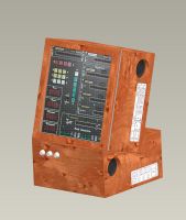
| 3/20/2011 | By end of 2010 there was an auction on Liquibiz which listed CRPMD displays. This acronym stands for
Combined Radar and Projected Map Display and it is the central display
in the Tornado's back cockpit and by the way
the biggest unit in the cockpit.
The German electronics company Helmut Singer Elektronik won the auction and I bought one of these from them. It consists of an analog storage CRT tube whose image, delivered by the radar, is projected to the frosted screen where it is overlayed with a projection of a standard 35 mm dia film. Only a small portion of the film, given by the selected scale, is projected and the main computer adjusts the projected area and the rotation of the complete projection unit to align the map with the aircraft position being in the center of the screen and the flight path pointing upwards. If the aircraft moves, the film is moved as well and from time to time there is heavy winding since the map consists of many stripes. By detaching the CRT assembly from this extremely heavy unit (>35kg) it is easy to "project" own images to the screen and I assume a bright LCD will do, too. Although I think the German Tornados still use this type of CRPMD, the British ones might have undergone update utilizing a LCD display (see TARDIS). Any information on this unit (NSN 5841-99-991-1833, Ferranti Part.No. 3892/72000-02-011) or the closely related RPMD (NSN 5826-99-573-1589, Ferranti Part.No. 3892/75500-02-010) is highly appreciated since I do not want to start a bigger reverse engineering project on this one now. |
![[CRPMD-Boxed.jpg]](http://www.programmer-electronic-control.de/pics/CRPMD-Boxed.jpg)
![[CRPMD.jpg]](http://www.programmer-electronic-control.de/pics/CRPMD.jpg)
![[CRPMD-storageCRT.jpg]](http://www.programmer-electronic-control.de/pics/CRPMD-storageCRT.jpg)
![[CRPMD-Fake.jpg]](http://www.programmer-electronic-control.de/pics/CRPMD-Fake.jpg)
| ||||||||||||||||||||||||||||||||||||||||||||||||||||||||||||||||||
| 4/18/2011 | The final front panel for the PEC's Operators Panel arrived from the
workshop. It was reliefing to see
that all parts fitted in very well after it took several weeks for the QCAD drawing to materialize.
Because the front panel is made from rather thick Al (5 mm), I used a milling machine to reduce the size where the displays need more room to increase the viewing angle. Later a wooden box will follow covering the rear side where all the electronics will be mounted. |
![[PEC-OMP-Panel.jpg]](PEC-OMP-Panel.jpg)
![[PEC-OMP-Milling.jpg]](PEC-OMP-Milling.jpg)
![[PEC-OMP-View.jpg]](PEC-OMP-View.jpg)
| ||||||||||||||||||||||||||||||||||||||||||||||||||||||||||||||||||
| 4/20/2011 to 4/24/2011 |
Over the last ten years Prof. Simon Lavington wrote a awesome book on the Elliott Brothers
company. The launch of this
book and the talk he gave on 21st of April in the London Science Museum was a perfect reason to visit
London again. This time my wife Pia was with me and apart from joining the CCS talk we had a great time
sightseeing in London and we spent a great day walking and picknicking with Terry and Val.
The weather was phenomenal and thus the walk along the Thames, the visits of the Tower, the Tower Bridge, the National Gallery, the museums in Greewich and may other places was a great experience. BTW: I had the opportunity make some input to Simon's book, especially to the Appendix 6 which can be viewed online on Springer's web page. |
![[MovingTargets.jpg]](http://www.programmer-electronic-control.de/pics/.catalogimages/MovingTargets-jpg-indexicon.jpg)
![[Sightseeing.jpg]](http://www.programmer-electronic-control.de/pics/Sightseeing.jpg)
![[Thames-Ride.jpg]](http://www.programmer-electronic-control.de/pics/Thames-Ride.jpg)
![[TowerBridge-Engines.jpg]](http://www.programmer-electronic-control.de/pics/TowerBridge-Engines.jpg)
| ||||||||||||||||||||||||||||||||||||||||||||||||||||||||||||||||||
| 5/20/2011 | During the last weeks a lot of time went into analyzing and understanding the
MECSL (=Marconi-Elliott-Computer-Systems Ltd.) floating
point library for the 12/12 which survived in one of Terry's boxes. First I encountered issues
compiling the library (the original MECSL assembler
was somewhat different from the later assembler I got from Terry) and of course the floating point
number format as well as the way to use the library had to be figured out.
The really interesting point on this library is, that it is an interpreter which essentially behaves like a floating point processor or a microcode extension - at least for the basic functions. I.e. if you want to use floating point you do not have to call weired library functions all the time but one has to call a subroutine once which immediately returns. From now on, one can use ordinary assembler commands like ADD, MUL and DIV but they are not obeyed directly any more - the interpreter does the floating point arithmetics. Using a special function this mode can be terminated again if one is done with FP arithmetics. For me this is a really clever design from the 1970ties although the implementation is ... well, ... ugly. What followed was an investigation on accuracy (see pictures starting with MECSL-FLoatTest* for plots of relative accuracy for all relevant functions supplied by the library). The accuracy is usually around 1E-5, whereas from the bits in the mantissa I'd have expected a higher accuracy. Additionally there are systematic deviations in the EXP function and ranges of lower accuracy in LN, SIN, SQRT, ATAN and even the multiplication! A function for converting floats to integers actually is severely broken as very small floating point values get converted to big integers instead of zero! But a software report from those days states, that the library has probably not been used by customers, so perhaps it was not tested very well. An investigating how the numerical error builds up during the Savage benchmark shows, that accuracy is really bad - especially if compared to the same algorithm utilizing 5 digit arithmetics using Mathematica. Anyhow even modern software is not without pitfalls regarding accuracy as can be seen if the Savage error is plotted aversus the precision set in Mathematica: As the set precision is increased, the Mathematica relies too long on the IEEE floats before activating its own floating point arithmetics, leading to unexpected low accuracy (up to 4 orders of magnitude!) at certain precisions set! Last but not least: Speed. The library is faster than a Z-80 at 4MHz being programmed in assembler or the 68000 based TI-92+ using BASIC which finally is a cold comfort. Summary: During this investigation I really learned a lot on floating point numbers, their representation, several pitfalls and how arithmetics is done correctly (E.g. by the CORDIC method for trigonometric functions)! |
![[MECSL-FloatTest-Multiply-12-2.gif]](MECSL-FloatTest-Multiply-12-2.gif)
![[MECSL-FloatTest-Divide-13-2.gif]](MECSL-FloatTest-Divide-13-2.gif)
![[MECSL-FloatTest-QFMATH-Exp.gif]](MECSL-FloatTest-QFMATH-Exp.gif)
![[MECSL-FloatTest-QFMATH-Sqrt.gif]](MECSL-FloatTest-QFMATH-Sqrt.gif)
![[MECSL-FloatTest-QFMATH-ATan-2.gif]](MECSL-FloatTest-QFMATH-ATan-2.gif)
![[MECSL-FloatTest-QFMATH-Sin-2.gif]](MECSL-FloatTest-QFMATH-Sin-2.gif)
![[MECSL-FloatSavage.gif]](MECSL-FloatSavage.gif)
![[MECSL-FloatTest-QFMATH-Ln-1.gif]](MECSL-FloatTest-QFMATH-Ln-1.gif)
![[MECSL-FloatTest-QFMATH-Ln-2.gif]](MECSL-FloatTest-QFMATH-Ln-2.gif)
![[MathSavage05.gif]](MathSavage05.gif)
![[MathSavage13.gif]](MathSavage13.gif)
![[MathSavage60.gif]](MathSavage60.gif)
![[MathSavage200Iterations.gif]](MathSavage200Iterations.gif)
| ||||||||||||||||||||||||||||||||||||||||||||||||||||||||||||||||||
| 6/2/2011 | Another update of Sim900al-NT-R: Version 1.3 has changed behaviour upon the 15 7168 instruction (terminate interrupt) of the 900 series: If encountered at base level, operation continues at base level. This allows the simulator for the 12 bit machines (like PEC) to be operated within the 18 bit simulator even with single stepping. I used this to learn how the 1971 MECSL floating point library has to be used. | | ||||||||||||||||||||||||||||||||||||||||||||||||||||||||||||||||||
| 6/23/2011 |
Speaker attached to the PEC-Panel (Yes, computers of those days always had
a speaker to hear what is going on and allowing trained technicians to hear
what the problem is) and implemented code in one
of the CPLDs to convert PEC's memory transfer signal to an audible signal
sounding similar to Terry's 920 whose sound I recorded during my visit in
2010.
Here is a recording from today what PEC sounds like in compiling software: For the first fraction of a second (0.0s-0.9s) you hear background noise of the SparcStation and me pressing the Enter key. This makes the first/old Transputer writing the inital instructions into PEC (0.9s-1.2s) and launching them. Now PEC starts loading the assembler (aka SAP, the Symbolic Assembler Program) from the virtual paper tape being simulated by the second Transputer within the new BlinkenLights (finished at 4.3s) which is automatically started afterwards. The assembler now waits until the operator places the first source tape into the reader (of course in my setup the BlinkenLights Transputer does this automatically) and acknowledges this by toggling key 11 on the word generator. This waiting leads to a regular sound (4.3s-5.8s) until I manually toggled the switch on the panel. From than on, PEC reads the source tape for the first pass until the very end of the recording. To compile larger software the operator would have to feed in all source tapes one by one acknowledging each by toggling key 11. After this, all tapes have to be fed in again in the same order for the second pass during which the binary is simultaenously written to the punch. This binary tape usually contains a loader and thus can be loaded via the initial instructions as was the assembler before. On the rear side of the PEC-Panel, one can see the new Transputer (top-left) with the selfmade CPLD interface which will finally take all functions from the old Transputer PCB (Lower-right PCB shown here). But for the time being, both Transputers are needed - but this poses no problem at all. The mainboard with the bunch of PCBs plugged in is the interface which connects the Transputer to PEC via Altera CPLDs (MAX7192SQC-15 and -7) and which is doing the hard real-time stuff. |
![[PEC-OMP-Guts.jpg]](PEC-OMP-Guts.jpg)
![[PEC-OMP-1stTest.jpg]](PEC-OMP-1stTest.jpg)

| ||||||||||||||||||||||||||||||||||||||||||||||||||||||||||||||||||
| 9/29/2011 | Together with a friend
we had placed a bid on an eBay auction on a big lot
(1000kg+) of Rolms, cables and related parts. On this day we met at the sellers
warehouse south-east of Munich and apportioned the haul. I got two additional
Rolm 1602s (plain ones, i.e. not -A or -B models with the 5605 CPU set but with
the CPU made of 9 cards full of TTL chips) and some cables whereas my companion
got lot of -B models and
cabinets. Apparently the seller's father had bought these Rolms (originating probably from the German Marine) via VEBEG. Together with the 1602 I imported from the US and which had been in use at the NASA's space flight center in Goddard, three 1602s are waiting to be inspected and fired up. |
![[RolmGitterBox1.JPG]](RolmGitterBox1.JPG)
![[RolmGitterBox2.JPG]](RolmGitterBox2.JPG)
| ||||||||||||||||||||||||||||||||||||||||||||||||||||||||||||||||||
| 10/22/2011 | Started reverse engineering of the WFG1, the graphics generator driving
the two CRT displays in the rear cockpit of the early Tornado aircraft.
Probably the German birds still use those? The setup consists of a sparc station 20 connected to a CPLD via a printer port SPI link. The CPLD is programmed to generate the bit-serial, differential data words sent to the wave form generator. Several wires are connected to the guts of the WFG1 monitor the incoming signals and the resulting internal activity within the circuitry. Upon sending random datagrams there is lot of activity (not only electronic signals, but also on modified TV monitor connected to the output). Internally to the waveform generator are several subunits, several euro card size PCBs each, being responsible for characters, circles, lines and tables. But there is NO DISPLAY memory, i.e. all graphical elements are computed as the electron beam moves across the screen! It will be fun to figure out the "language" the engine of the waveform generator will understand to generate meaningful output! |
![[WFG-Abgriffe.jpg]](WFG-Abgriffe.jpg)
![[WFG-RandomDatagram.jpg]](WFG-RandomDatagram.jpg)
![[WFG-Datagram-Setup.jpg]](WFG-Datagram-Setup.jpg)
Video -> 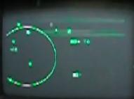 <- Video <- Video
| ||||||||||||||||||||||||||||||||||||||||||||||||||||||||||||||||||
| 12/10/2011 | Finalized the design of a housing for PEC-OMP (PEC-Operator and Monitor Panel) using CAD system Pro/E: The housing will consist of two parts: A lower one taking a 500W inverter built around a motor AC drive followed by a homebrew sine filter. The upper part will take the panel, Transputer and interface electronics and will be protected by a glass cover. Now search for a carpenter willing to make the cabinet from my drawings will start (This will not be easy as I need only one unit and they all have plenty of work). |
| ||||||||||||||||||||||||||||||||||||||||||||||||||||||||||||||||||
| 12/17/2011 | First success on deciphering the WFG1's language: After some painstaking
experiments and analysis of the WFG's reaction to bombardment with random
bit patterns it now is obvious that there are 5 command groups and one
of the groups drives the text engine. 64 different characters can be
displayed simultaneously on the two screens and one 32 bit command
is able to write 3 successive characters onto the screen. 8 bits are used per character,
but only 6 bits encode the character whereas 2 encode the attributes "size" and
"reverse". The trains of characters can be placed arbitrarily onto the
screen by giving line and row numbers, where the next train is to
be placed. The waveform generator has got a busy output, but text is processed immediately and thus characters can be moved around in breathtaking speed! |
Video -> 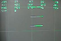 <- Video <- Video
| ||||||||||||||||||||||||||||||||||||||||||||||||||||||||||||||||||
2012 |
2012 |
2012 | ||||||||||||||||||||||||||||||||||||||||||||||||||||||||||||||||||
| 2/20/2012 | Together with the other lucky Rolm owner
we visited the PWA electronics
in Seligenstadt: They supported the European Rolm systems until they where
taken out of service. PWA supplied us with some spares and valuable
information on the 1602s - many many thanks! My friend even got a
complete MILTOPE floppy disk drive... Although we did some work on his Rolms we have not been able to bring the drive up this time. |
| ||||||||||||||||||||||||||||||||||||||||||||||||||||||||||||||||||
| 3/3/2012 | Completed design and assembly of a paper tape simulator for the
Rolm 1602: The simulator is being plugged between the Rolm and a
printer port, simulating a Centronics printer on the PC side. In my
setup I use a Netgear PS101 Ethernet print server to access the Centronics
port via TCP/IP and thus the simulator shown essentially is a TCP/IP
interface to the Rolm's paper tape input. Using this setup I successfully ran Fig Forth on the smallest of my 1602s (8k, no extension cabinet). But I still wonder whether there is any useful program which can be ran on this Forth? Getting more familiar with the Rolms I realized, that I have got the microcode extensions for floating point commands (Hybrid Memory, option 22) and the access protection module (Hybrid Memory, option "special"). The latter comes with an additional module (called APM for the CPU set: Hey, this provides memory-protection, IO-protection and introduces a super-user mode for the 1970ties Data General computer architecture! |
![[Rolm1602-PTRsim1.jpg]](Rolm1602-PTRsim1.jpg)
![[Rolm1602-PTRsim2.jpg]](Rolm1602-PTRsim2.jpg)
![[Rolm1602-Setup.jpg]](Rolm1602-Setup.jpg)
| ||||||||||||||||||||||||||||||||||||||||||||||||||||||||||||||||||
| 4/17/2012 | Final release of the simh binary for the Rolm (sorry, only IRIX tardist at the moment): This binary contains a bugfix to the Nova "boot cpu" command and includes the original boot code residing on the 1621 "Hybrid Memory" modules marked "option 6" of the early Rolm 1602 (not -A or -B variants). Using this version, realistic testing of code compiled for stand-alone Rolms is possible. |
| ||||||||||||||||||||||||||||||||||||||||||||||||||||||||||||||||||
| 6/12/2012 | In March there has been a big lot of Tornado surplus from the
Bundesluftwaffe for auction on VEBEG. Included have been 27 TV/Tab
displays (NSN6625-12-186-7800, Cage Code K0 656, Part Number V22.498.85).
The electronics dealer against "throw-away-ism",
Helmut Singer Elektronik, got the whole lot. In this way I acquired a TV-Tab
display which has a NATO list price of more than 33852,64EUR ;-) This display will match the WFG1 perfectly and hopefully the winter will give me more time for reverse engineering its command set... Analysis upon connecting these to WFG in 2013 revealed the following pinout: 65, 66, 76 three phase input 208V at 400Hz and neutral line on 75 (mandatory!). For switching on, also needed are 28V on 67 with return line on 46 (only than the internal relay can be engaged). They accept the standard line and frame rates as TV is specified (15625Hz line and 50Hz frame frequency) and these are supplied via 18/19 (line/!line) and 21/22 (frame/!frame) as standard differential signals (WFG channel; RCN channel given 2013). |
![[TV-Tab-1.jpg]](TV-Tab-1.jpg)
![[TV-Tab-2.jpg]](TV-Tab-2.jpg) | ||||||||||||||||||||||||||||||||||||||||||||||||||||||||||||||||||
| 8/14/2012 | The housing of the PEC-OMP was completed by the carpenter and together with my father in law we went to Landsham and picked up the empty PEC-OMP. Mr. Huber from Holz Design Huber really did a great job - Thank you very much! | ![[PEC-OMP-1.jpg]](PEC-OMP-1.jpg)
![[PEC-OMP-2.jpg]](PEC-OMP-2.jpg) ![[PEC-OMP-Test.jpg]](PEC-OMP-Test.jpg)
| ||||||||||||||||||||||||||||||||||||||||||||||||||||||||||||||||||
| 9/22/2012 | Populating the PEC-OMP cabinet with the 400Hz three phase inverter
I ran into trouble with 15kHz noise of the PWM inverter being injected
into the ground line. The crossfeed is caused by the Y capacitors being
part of the EMC protection within PEC's power supply and causes the
personal protection switch to interrupt mains. I did not discover this
earlier since during pretests an isolation transformer was always used. Another problem is that without galvanic isolation, the sine filtered output is either centered around ground potential (good case) or is "riding" on the phase potential (bad case) depending on the orientation the mains plug is inserted. In the latter case and together with remaining noise from the PWM signal, the isolation of PEC has to withstand 500V to ground which gives me the creeps. After several requests and quotations I ordered a custom made 3 phase isolation transformer to be added to the inverter cabinet hopefully solving both issues within the next 6 weeks. |
![[PEC-OMP-Inverter1.jpg]](PEC-OMP-Inverter1.jpg)
![[PEC-OMP-Inverter2.jpg]](PEC-OMP-Inverter2.jpg)
| ||||||||||||||||||||||||||||||||||||||||||||||||||||||||||||||||||
| 9/24/2012 | Mr. Hans Kiening, who got aware that I am
interested in the moving map displays by looking at this page, called me via
telephone: He
invented the digital machinery and algorithms to expose the movig map films for the
Ferranti displays used in Tornado (and maybe others). On 12/2 we met and I learned a lot on the "story" of this development as Mr. Kiening presented pictures of the setups and cameras used to rectify the paper maps and check the resulting films. Given, that it was in the 1980ties and that most machines up to this time where purely mechanical, e.g. using complicated motion links, this was a huge step forward. Inspired by this I started to look into the details of the RPMD projector from the Tornado's front cockpit. This projector is a box full of synchro-resolvers, delicate mechanics, optics and some electronics. There is even a lamp magazine allowing the lamps being automatically changed on the fly without any intervention. A good starting point to learn more on Mr. Kiening is the web page of his company KODIKA or to have a look at his ingenious patents. |
![[Kodika-PVG-400-0.jpg]](Kodika-PVG-400-0.jpg)
![[Kodika-PVG-400-1.jpg]](Kodika-PVG-400-1.jpg)
![[Kodika-PVQ-400.jpg]](Kodika-PVQ-400.jpg)
![[Kodika-Kopierstation.jpg]](Kodika-Kopierstation.jpg)
![[KodikaSample-0.jpg]](KodikaSample-0.jpg)
| ||||||||||||||||||||||||||||||||||||||||||||||||||||||||||||||||||
| 11/6/2012 | Together with a friend (we call ourself the "FINner"s to express our interest in the Ferranti made Inertial Navigation systems) we suceeded in firing up the Ferranti inertial navigators. Of big help was a test set we happily obtained from a VEBEG auction. This was an awesome whole-day session which culminated in running one of the platforms removed from its normally gas filled enclosure. This gave us the unique possibility to observe the holy grail of inertial navigation: The Gimbal-Flip. |
Video showing me moving the running FIN1010 platform: ![[FIN1010-Platform-20121106.divx]](.catalogimages/FIN1010-Platform-20121106-jpg-indexicon.jpg)
| ||||||||||||||||||||||||||||||||||||||||||||||||||||||||||||||||||
2013 |
2013 |
2013 | ||||||||||||||||||||||||||||||||||||||||||||||||||||||||||||||||||
| 2/5/2013 | Second visit to Mr. Kiening from KODIKA (see 9/24/2012) - this time
I carreid a roughly working RPMD with me to test it on some vintage
experimental film strip and it worked great. It was quite tricky to
insert the film as I had pulled out the "helper strip" by accident.
Many thanks for this nice afternoon, the lot of lessons learned
and for the test film! Update 7/8/2020 upon request (minor amendments 11/10/2021): The reverse engineered pinout from 2013 of the RPMD display is as follows: 115VAC/400Hz: 3, Neutal: 2, +28V: 17, 4, GND: 1, 32 (The unit requires 120W on the AC line and the internal PWM dimmer for the lamp causes severe feedback, which some electronic inverters do not like). A reference input of 26VAC/400Hz is required on pins 48 and 49 (not floating, but symmetric to GND, pin 47, to make the demods work). The unit is driven by 5 (yes, FIVE!) resolver inputs (i.e. sin/cos signals; the common pin is shown in bold face in the following): The "short" axes are N/S (Pins 54, 55 and 56) and HEADING (Pins 43, 44 and 45) whereas the "long" axis with a maximum of 12m film are encoded using three signals to achieve the required precision (Coarse: 64, 65 and 66; Medium: 59, 60 and 61; Fine: 51, 52 and 53). Chassis can be connected at pin 9. Finally pin 42 is the mains-on input (28V applied there engages a relay powering up the unit). CAUTION: All above without warranty! Update 5/28/2023 another update upon request (to support David's great work): There are 5 outputs of the display for reading the switches, pins 34&35 encode scale, 36, 37 and 38 the function selected. Pulling pins 40 or 41 high engages the lamps for STB and NTH UP (north up). Probably pin 30 is a input into the RPMD inhibiting the map drive and pin 10 controls DAY/NIGHT. CAUTION: Again no warranty! Explanation 5/29/2023: There is really huge interest regarding that display - How do the three cascaded resolvers for the long axis of the film work? There is a diode matrix on the X error amp ensuring the coarse range has precedence. So that one gets nulled first (+/-90 degrees give the full length of the film of max. 12m). After error output of coarse is close enough to zero, the mid range resolver's error output becomes important and movement goes on until that one is getting close to zero (approx 30 rev. per one on coarse). Finally both coarse and med error signals are close to zero and only the error output of fine is reduced by slower movement (again approx. 30 rev. per one of medium). In that way, one gets ABSOULUTE positioing with better than 0.05mm on 12m of film - 1:240000 resolution or ca. 20 bits - All that is implemented in my Interfacebox since 2016! More precise factors 6/27/2023: The 30 given on 5/29/23 are only approximate (as stated). More precise values are 32.2727272727/1.00979 (med/coarse) and 1041.5289256198/1.00979/1.00333 (fine/coarse). First number determined by from counting tooth on the cogwheels, additional factors are corrections applied later from experiment. |
![[Kodika-Meeting.JPG]](Kodika-Meeting.JPG)
![[RMPD-SynchroTest.JPG]](RMPD-SynchroTest.JPG)
![[Making-of-RPMD-Films.jpg]](Making-of-RPMD-Films.jpg)
| ||||||||||||||||||||||||||||||||||||||||||||||||||||||||||||||||||
| 2/9/2013 | An other avionics enthusiast from Leipzig (now also a FINner) gets in
touch with me after having seen this page. Now we are three people interested in vintage
inertial navigation kits (especially the FIN1010/1012) actively working on the
units. An idea starts
to emerge: Why not building a device doing the following jobs: Reading the information
sent by the FIN1010/FIN1012, logging it to SDcard (or whatever) and displaying
the current position e.g. via NMEA and a suitable map
software on some attached device? Of course my additional goal is to drive one of the moving map displays from this device! |
![[FIN1010online-CDU.JPG]](FIN1010online-CDU.JPG)
| ||||||||||||||||||||||||||||||||||||||||||||||||||||||||||||||||||
| 4/20/2013 | The analysis of the WFG1 is completed and control of all elements
via the Panavia link is possible now (3 circles, 20 lines, tabular characters, random characters
in two sizes and the grid parallel on either display 1 or 2). The initial fear that there may be
something wrong with the WFG was eliminated by testing a second WFG which
Simon Green from Hayward and Green
Aviation sent me on 3/10/2013. I just had not
fully understood how lines are generated and there was a bad solder
joint in my setup. Many many thanks for this help to Simon and hopefully the Bavarian Weissbier tasted good ;-) The next project in this line is the analysis of the TV-Tabs to connect them to the WFG ... to be started on the next weekend with bad weather. |
![[TestWFG-SimonGreen-20130408.JPG]](TestWFG-SimonGreen-20130408.JPG)
Short Video | ||||||||||||||||||||||||||||||||||||||||||||||||||||||||||||||||||
| 5/4/2013 | The PEC-OMP's panel gets populated. PCBs, power supply, fan, Transputer and SCSI-Transputer-Interface get mounted. As the original 902, the PEC-OMP gets a speaker allowing to hear what the unit is currently doing. To ajust the volume an additional potentiometer had to be added to the machined front panel as I had forgotten this in the design. |
![[PEC-OMP-Assembly0.JPG]](PEC-OMP-Assembly0.JPG)
![[PEC-OMP-Assembly1.JPG]](PEC-OMP-Assembly1.JPG)
![[PEC-OMP-Full.JPG]](PEC-OMP-Full.JPG)
![[PEC-OMP-Open.JPG]](PEC-OMP-Open.JPG)
![[PEC-OMP-Panel.JPG]](PEC-OMP-Panel.JPG)
![[PEC-OMP-Speaker.JPG]](PEC-OMP-Speaker.JPG)
| ||||||||||||||||||||||||||||||||||||||||||||||||||||||||||||||||||
| 6/16/2013 | It's christmas again as a delivery from Helmut Singer arrives:
We FINners receive new toys which are compatible
to the FIN1010/1012 systems. So the Ferranti test set, the display units and
our homebuilt tools work right out of the box. On 6/27/2013 one of these
toys has had its first ride in a BMW to proove that it is working ;-)
Ideas what the logging device is to look like and the features are recorded and developed using a shared document. The plan is to have NMEA output, touch screen control and display, logging to SDcard and on board GPS, magnetic sensors and MEMS inertial senesors for reference. A bluetooth output will provide map display on any smart phone. |
![[LINSonline-CDU.JPG]](LINSonline-CDU.JPG)
![[LINS-Opened.JPG]](LINS-Opened.JPG)
| ||||||||||||||||||||||||||||||||||||||||||||||||||||||||||||||||||
| 8/18/2013 | Analysis of the TV/Tabs is complete. The CRT based one had an internal
fault which had to be fixed first, but now the original CRT TV/Tab and
the later MLU version from the scrapped ADVs work on my WFG1. The
mechanism how keyboard data can be read out is analyzed, too. To achieve the ultimate goal of connecting this graphical subsystem to the PEC, a special setup for cooling the WFG and a stronger power supply has to be set up if WFG shall be operational for longer periods driving two displays (WFG+2*TV/Tab will needed around 450W of 3 phase 208V).
Upon request (6.6.2019) here the basic pinout needed to drive either
version (CRT or LCD) of the display in most basic mode as I figured it out by my
analysis (looking at PCBs, measurements and used in the tests shown in the
pictures on the right side - no guarantee): 65, 66, 76: R,S,T of 208V three
phase, 400Hz; 75: N (yes, they really require a neutral line!); 94(-),95(+): VSYNC
in of the RCN channel; 96(+),97(-): FRAMESYNC in of the RCN channel; BNC E
(rear side): Video Input from WFG (always routed to display). Using these a
video image can be displayed if the RCN button is pressed. The keyboard can
be read out via 14/15: Data, 23/24: CLK as ordinary Panavia Link
datagrams. Update 10/06/2021: For those interested in TV/Tabs (and other RF and avionics stuff), the excellent page of Jacob is a must-read. He recently made a very thorough analysis and documentationof the CRT based TV/Tab and for sure there will be more coming! Thanks Jacob for the great work! |
![[TV-Tab-CRT-OnWFG.JPG]](TV-Tab-CRT-OnWFG.JPG)
![[TV-Tab-Comparison0.JPG]](TV-Tab-Comparison0.JPG)
![[TV-Tab-Comparison1.JPG]](TV-Tab-Comparison1.JPG)
![[TV-Tab-TFT-TestPattern.JPG]](TV-Tab-TFT-TestPattern.JPG)
![[TV-Tab-TFT-OnWFG.JPG]](TV-Tab-TFT-OnWFG.JPG)

| ||||||||||||||||||||||||||||||||||||||||||||||||||||||||||||||||||
| 10/14/2013 | Terry Froggatt sent me a new program to run on the PEC! There is a prehistory to this: After I ported Terrys and Dons simulator for the 18 bit Elliotts to modern gnat Ada and made this public, Terry told me that he wrote a BASIC interpreter for the 920 decades ago. He donated me a version of this interpreter to be run within the 920 simulator by end of 2012 (many thanks!). This made me very happy and therefor I ported a vintage game (Tic Tac Toe from the well known book "101 Computer Games") to this BASIC in March. Having sent this over to Terry he ran it on the original machine which was way slower than in the simulator and requires minutes to play ONE game of Tic Tac Toe. So Terry ported the game to the 920's 18 bit assembler (called SIR) and to 12 bit SAP, which is somewhat different. Of course he had no hardware to test the 12 bit version, and I was deeply impressed that it worked perfectly on the original hardware in the second attempt - precisely on the afternoon of 10/20/2013. Many thanks and high esteem for this achievement - a new and useful piece of software written in assembler for a 50+ year old architecture indeed is a rarity! |
6 min video:
Sorry, it's not a good | ||||||||||||||||||||||||||||||||||||||||||||||||||||||||||||||||||
2014 |
2014 |
2014 | ||||||||||||||||||||||||||||||||||||||||||||||||||||||||||||||||||
| 1/25/2014 | The freshly restored Rolm MSE/14, which had a problem in the base memory
on the 1820 CPU board is completely up and running. It successfully booted
the IDMS menu from a 7300 EPROM board and some programs from paper tape via
a paper tape simulator. Running the 1553B diagnostics revealied, that even
one of the MIL-STD-1553B boards is still working and transmitted datagrams
showed up in both of the redundant links. Next step is to replace the old defunc lead batteries in the power supply by GoldCap capacitors to have memory backup after power loss - at least for some minuts. A future application of the 1553B probably is reading the Ferranti LINS (see 6/16/2013) via this interface, too. |
![[MSE14-Setup-201402.jpg]](MSE14-Setup-201402.jpg)
![[MSE14-Rolm1602-PTRsim-201402.jpg]](MSE14-Rolm1602-PTRsim-201402.jpg) ![[MSE14-GoldCap-201402.jpg]](MSE14-GoldCap-201402.jpg)
![[MSE14-1553B-Xmit.jpg]](MSE14-1553B-Xmit.jpg)
| ||||||||||||||||||||||||||||||||||||||||||||||||||||||||||||||||||
| 2/2/2014 | Test drive with a boot mounted FIN1010 connected to the now 80% completed logger interface, generating logs of the FINdata along with a GPS track. The challenge was to get the 300W power out of the car's electrical system without blowing the fuses. It worked nicely until we ran into an over temperature problem with the FIN. Accuracy was quite impressive for a over 30 year old system! |
![[FIN-CPLD-PCB.JPG]](FIN-CPLD-PCB.JPG)
![[FIN-Logger0.JPG]](FIN-Logger0.JPG)
![[TestDrive-NormalAlign-Deviation-20140202.gif]](TestDrive-NormalAlign-Deviation-20140202.gif)
| ||||||||||||||||||||||||||||||||||||||||||||||||||||||||||||||||||
| 2/21/2014 | On eBay I got hands on the original "User Interface" for the PEC, i.e. the original cockpit panel from the Tornado's rear cockpit. The panel arrived on Tue/20 and since yesterday parts of the circuit are already reverse engineered: The digital serial link of the panel seems to match the PEC's slow link and the own PEC-TOS (PEC-Trivial-Operating-System) now has an interrupt driven driver for this link which sends arbitrary data to the panel. The next days will be exciting as powering up, testing and connecting the panel to PEC are impeding! |
![[AECM-Panel-Gr.1.jpg]](AECM-Panel-Gr.1.jpg)
![[AECM-Panel-Marked2.jpg]](AECM-Panel-Marked2.jpg) ![[AECM-Panel2.jpg]](AECM-Panel2.jpg)
![[AECM-Guts.jpg]](AECM-Guts.jpg) ![[AECM-Spy.jpg]](AECM-Spy.jpg)
| ||||||||||||||||||||||||||||||||||||||||||||||||||||||||||||||||||
| 4/9/2014 | My automated eBay search sent me an alarm as suspicious PCBs showed
up. They looked very similar to the ones I know from PEC, although they
are not completely identical. I bid on some of them and contacted the seller:
He actually sold me the complete box for a reasonable price and this is
how I got hands on 6605-99-525-8290, "DIGITAL COMPUTER UNIT" containing
the following 12 PCBs: 6605-99-529-2339, 6605-99-529-2338, 6605-99-529-2323,
6605-99-529-2323, 6605-99-529-2324, 6605-99-529-2337, 6605-99-529-2336,
6605-99-529-2336, 6605-99-529-2335, 6605-99-529-2322, 6605-99-529-2334,
6605-99-529-9118. Unlike PEC the DCU uses software stored in ROM
and has semiconductor RAM. Therefor this unit is not freely
programmable.
From an expert I got the information that the box was used on the NCS1 gyro compass system. It is indeed an other variant of the 12/12 processor and by 2014 some are still in use. Two great finds (1) a different 12/12 and (2) the 12 bit Elliott 900 series is still alive around 54 years after the first 900 machine was built! |
![[NCS1-DCU-1.JPG]](NCS1-DCU-1.JPG)
![[NCS1-DCU-2.JPG]](NCS1-DCU-2.JPG) ![[NCS1-DCU-3.JPG]](NCS1-DCU-3.JPG)
12/12 (NCS): 12/12 (PEC): ![[NCS1-Unit-TimingPCB.jpg]](NCS1-Unit-TimingPCB.jpg)
![[TornadoUnit-Timing.jpg]](TornadoUnit-Timing.jpg)
| ||||||||||||||||||||||||||||||||||||||||||||||||||||||||||||||||||
| 5/3/2014 to 5/4/2014 |
Participation in the Vintage Comuter Festival Europe (
VCFe 15.0)
in Munich with
poster
and a talk.
As preparation the homebrew tiny operating system for PEC got some updates and the code was cleaned up. An up-time clock with improved timer handling is added (the timer hardware within PEC really is a bitch) and the AECM panel can be used to start the user processes (currently just one using the plotter to plot a demo graphics). Version of the trivial operating system now is 1.11! But most important, all equipment survived the transfer to the festival and the two days of demonstration: PEC (Serial 129), Rolm 1602 (Serial 235) and Rolm MSE/14 (Serial 130). The exhibition was awarded the third price by the visitor's election at the end of the festival. |
pec-tos V1.11
| ||||||||||||||||||||||||||||||||||||||||||||||||||||||||||||||||||
| 6/23/2014 |
For several years two boxes sit in my shelf: They have identical
footprint and one is called Scot Rate Gyroscope (Light gray color,
Part. No. 229-057594)
containing three mechanical rate gyroscopes whereas the other one is
from Astrium (Black, NSN 5985-99-663-7691, Part. No. ARS-BA322) containing
three vibrating structure gyros from BAe systems. Analysis showed
both have the same differential analog current mode outputs and
that the later one has an additional RS-232 port, broadcasting turn
rate and temperature.
The mechanical one is really lousy regarding performance, but with the Astrium box one can after statistical data evaluation be sure that the Earth is still turning at 1+/-0.3 revolutions a day - Thank goodness! |
![[RateGyros-Plug.jpg]](RateGyros-Plug.jpg)
![[RateGyros-Testing.jpg]](RateGyros-Testing.jpg)
| ||||||||||||||||||||||||||||||||||||||||||||||||||||||||||||||||||
| 9/17/2014 |
During all past experiments it was always a challenge to get enough
400Hz 115VAC power for the various devices to play with. My home-brew
sinus inverter is maxed out at 100W and even less if the load is not
a purely ohmic one.
Today the new 1500W power inverter is completed and operated one of the TV/Tab displays and the WFG simultaneously. It consists of a standard PWM inverter (e.g. a SV-iC5, capable of 400Hz at >15kHz PWM frequency) as for example used in metal working machines. This is followed by a sinus filter (e.g. 3AFS400-007.400, suitable for up to 400 Hz) and an isolation transformer to give 115VAC single phase, 115VAC three phase in star configuration or 208V three phase into a triangle (The 400Hz and Dy5n are important. The star configuration is necessary for many avionics devices, e.g. the LN-3). The transformer was custom made by the Tauscher company to my own specification. The new inverter also supplies 28V essential DC needed by some units. Last but not least the very nice wooden housing was a birthday present from my father-in-law: Many thanks therefore, it its a great machine now with an extremely nice front panel! I took advantage of the situation to harmonize my 400 Hz connections: All devices use the same AB05 plug as used on PEC now, so all inverters/supplies can be interchanged now only one type of extension cable is necessary. |
![[Inverter1500-Testing.jpg]](Inverter1500-Testing.jpg)
![[Inverter1500-TopView.jpg]](Inverter1500-TopView.jpg)
![[TVtab-Test20141015.jpg]](TVtab-Test20141015.jpg)
![[Inverter1500-Housing1.jpg]](Inverter1500-Housing1.jpg)
![[Inverter1500-Housing2.jpg]](Inverter1500-Housing2.jpg)
| ||||||||||||||||||||||||||||||||||||||||||||||||||||||||||||||||||
| 9/30/2014 |
On the VCFe, Andre showed his experimental Nova HDD simulator and
together with the experimental cabling I prepared, we
have been able to write and read the MSE14s memory from Andre's simulator
on the second day of the VCFe.
So we decided, to start a joined project of building a rather capable simulator together where Andre would be the software man, Guenther is responsible for the housing and I am going to take care of hardware. Development progressed extremely smooth (better than in any company I know) and after just four months first hardware works. |
![[EB-HDDsim0-Dev.jpg]](EB-HDDsim0-Dev.jpg)
| ||||||||||||||||||||||||||||||||||||||||||||||||||||||||||||||||||
| 10/20/2014 |
The HDD simulator advanced quickly and for the first time my mil-spec
eclipse booted into RDOS right from the SD card within the hard disk
simulator as did a 1602 with 32k of core memory. The HDD simulator also
offers a TTY1 interface and PTR/PRP which are routed to sockets on
an Ethernet port. This feature makes data exchange between the real
machines and simh highly comfortable.
By this occasion I checked my various memory chassis and repaired a 8k and 16k expansion chassis which I got from Guenther on the VCFe - many thanks therefore! My 1602 runs nicely in short- (8kW), med- (16kW) and long-body (32kW) configurations now. |
![[EB-Rolm2-HDDsim.jpg]](EB-Rolm2-HDDsim.jpg)
![[MSE14-CPU-Arithmetics-Memory.jpg]](MSE14-CPU-Arithmetics-Memory.jpg)
![[MSE14-CPU-Microcode-Integer.jpg]](MSE14-CPU-Microcode-Integer.jpg)
![[MSE14-Eclipse.jpg]](MSE14-Eclipse.jpg)
![[EB-Rolm0-32kW-NASA.jpg]](EB-Rolm0-32kW-NASA.jpg)
![[EB-Rolm2-08kW.jpg]](EB-Rolm2-08kW.jpg)
![[EB-Rolm2-16kW.jpg]](EB-Rolm2-16kW.jpg)
![[EB-Rolm2-32kW.jpg]](EB-Rolm2-32kW.jpg)
| ||||||||||||||||||||||||||||||||||||||||||||||||||||||||||||||||||
| 10/31/2014 |
On a trip to Guenther near Frankfurt I visited the PWA electronics
where the CEO kindly offered me to go "shopping" in his remaining
Rolm stock before the PWA will part with it. I picked some of
the most interesting things for me: Some documentation, spare
IO PCBs, paper tapes and a PC called the "Rolm-Mother" (see later). There have
been enough parts to compile a very complete 1602B including spares,
which I sent to Andre on the other end of Germany distributed over three
very heavy parcels.
Guenther supplied Andre with a blinkenlights panel and since beginning of December Andre has got a working Rolm 1602B. The remaining Rolm parts from PWA have been distributed between the RuAG, some former PWA customer in the UK and a collector at the Computer Cabinett in Goettingen. |
![[RolmHaul2014.jpg]](RolmHaul2014.jpg)
![[Rolm1602B-for-Andre.jpg]](Rolm1602B-for-Andre.jpg)
| ||||||||||||||||||||||||||||||||||||||||||||||||||||||||||||||||||
| 11/1/2014 |
On the way back from Frankfurt I visited Guenther where we set up his
HDD simultaor and now there are three running HDDsim`s throughout Germany and
probably the only still running 16 bit Rolms on the world: 2*1602B
one in Bremen and another in Frankfurt, MSE14 in Munich and 1602 in
Marktoberdorf. Guenther's Rolm 1602B has a somewhat strange IO plug configuration so we had to make some special cabling "on the fly". |
![[Rolm1602B-Guenther.jpg]](Rolm1602B-Guenther.jpg)
| ||||||||||||||||||||||||||||||||||||||||||||||||||||||||||||||||||
| 11/17/2014 |
From PWA I got the "Rolm-Mother" - an ordinary PC which was used in
the Rolm factory for checking new and repaired machines. Plugging
special IO-PCBs into the machine this PC allows booting the Rolm
into the IDMS (Integrated Diagnostics and Maintenance System) and
running any diagnostics available. Together with IO- and Channel-Test-PCBs
nearly all IO-PCBs and processors ever supplied by Rolm can be tested.
Today the MSE14 booted successfully into IDMS and executed most
tests with positive result.
Only the mapped memory shows an error (hence only 32kW mounted on the CPU available, but none from the external 1861 PCB -> no mapped RDOS for now). Now I have some diagnostics in form of paper tape from this year's visit at PWA and of course after reading in and lauching them, they appear to be identical to what the IDMS offers in an extremely elegant way. |
![[RolmMother-PC.jpg]](RolmMother-PC.jpg)
![[EB-MSE14-Motherboot1.jpg]](EB-MSE14-Motherboot1.jpg)
![[EB-RolmTapes.jpg]](EB-RolmTapes.jpg)
![[EB-RolmTapes-Reading.jpg]](EB-RolmTapes-Reading.jpg)
| ||||||||||||||||||||||||||||||||||||||||||||||||||||||||||||||||||
| 12/6/2014 |
During my visit at Guenther he donated me a big PCB with many cables
attached and quite some LEDs. This weekend I analyzed it and I am
sure now that this is a microcode development kit for the 1602: It
replaces the processor's microcode PCB (position CPJ of the nine
cards making up the processor). It supplies the same microcode
PROMs as the original one, but additionally has RAM to fill the
upper BANKs of the microcode address space. It offers micro break-points
and micro-single-stepping and I already built a small control
panel for it.
Programming of the microcode RAMs was almost surely done using a second Rolm processor being connected to two of the cables (two-plug IO connection type). I fixed some obvious defects, but still the board draws a lot of current and freezes the processor it is plugged in. So repairing this, figuring out how microcode is programmed and writing a microcode assembler will be a major task for the future. Nevertheless this is a highly interesting and unique artifact from the 1970ties: I do not know of any microcode development kit (hardware) for any architecture from that era that survived. Contact me to prove me wrong ;-) Update 2021/10/06: Had some exchange with Jos who is not only taking care of one of the few remaining Lilith computers, but is also working on restoring a Rolm 1602A he recently acquired. He mentioned that for the Lilith there also was a hardware microcode tool which did not survive, but the complete software kit did - and he even created a modified microcode to drive an IDE harddrive on the Lilith which is amzing. So there is a 2901 based architecture where at least the software tool-kit survived. Hence at some time I must fix and fire up my hardware microcoder - until then: Any more survivors? |
![[Homebrew-MicrocodePanel.jpg]](Homebrew-MicrocodePanel.jpg)
![[RolmMicrocoderComplete.jpg]](RolmMicrocoderComplete.jpg)
![[EB-HDDsim-on-1602-w-Microcoder.jpg]](EB-HDDsim-on-1602-w-Microcoder.jpg)
| ||||||||||||||||||||||||||||||||||||||||||||||||||||||||||||||||||
| 12/15/2014 |
Using IDMS and a 3761 PCB obtained via eBay, the MSE14 passed
the 1553B diagnostics: The mil-spec 1553B network implemented
on the 3761 sent and received packets at 1Mbit data rate. This
implementation of the 1553B is especially interesting as the 3761
is a complete processor built from AMD bit slice chips and
it is using the main memory of the host via DMA. So here we
have an early form of multi-core with shared memory and up to
three of these PCBs have been supported per processor, making
such a machine a quad-core beast ;-)
I also replaced the dead lead batteries in the MSE14's power supply by gold cap capacitors. These give memory backup for around two minutes of power outage and are an elegant solution to the problem of leaking batteries. |
![[1553B-ModuleTest-in-1602.jpg]](1553B-ModuleTest-in-1602.jpg)
![[Rolm3761-1553B-PingPong.jpg]](Rolm3761-1553B-PingPong.jpg)
![[MSE14-AccuReplacement1.jpg]](MSE14-AccuReplacement1.jpg)
![[MSE14-AccuReplacement2.jpg]](MSE14-AccuReplacement2.jpg)
![[MSE14-AccuReplacement3.jpg]](MSE14-AccuReplacement3.jpg)
| ||||||||||||||||||||||||||||||||||||||||||||||||||||||||||||||||||
2015 |
2015 |
2015 | ||||||||||||||||||||||||||||||||||||||||||||||||||||||||||||||||||
| 1/20/2015 |
On eBay I hunted a cockpit voice recorder (CVR,
PartNo. 125250-3, NSN 5835-21-881-9325) from the early tornado.
These are tape drives using standard music cassette to record audio from
both pilots. An additional function was that the mission data (way points
etc.) prepared in advance had been fed from this unit into the main computer -
a function called data entry. Studying the recorder is complete and I can
record and replay audio data now: The track format of the tape is
rather strange as
both sides of the tape are used simultaneously, i.e. the tapes cannot
be flipped as usual audio cassettes. Additionally in data entry mode the
tape runs at twice the recording speed replaying a complete C-60 tape in
around 15 minutes.
One of the gearing mechanisms was completely destroyed so restoring this unit was a funny job and I recycled gears from a model locomotive to restore the recorder. It will be a nice "mass" storage to be added to the PEC later... A video on YouTube (time reference 2:13-3:10) shows, how the CVR of the early Tornado is used to transfer way-point data from the briefing room into the memory of Tornado's main computer. It is really amazing that automatic low level flight below 300ft was safely possible using the 1970ties navigation suite and the terrain following radar system (look at the e-scope showing the radar data from the terrain following system at 5:20 min on YouTube). |
![[Leigh2.jpg]](Leigh2.jpg)
![[LeighCVR.jpg]](LeighCVR.jpg)
![[LeighLaufwerk.jpg]](LeighLaufwerk.jpg)
![[LeighMotors-Ritzel.JPG]](LeighMotors-Ritzel.JPG)
![[LeighRitzelvergleich.JPG]](LeighRitzelvergleich.JPG)
![[Leigh-VCRwithTape.JPG]](Leigh-VCRwithTape.JPG)
![[MotorPutt.JPG]](MotorPutt.JPG)
![[RitzelPutt.JPG]](RitzelPutt.JPG)
| ||||||||||||||||||||||||||||||||||||||||||||||||||||||||||||||||||
| 2/3/2015 |
MSE14 for the first time boots a mapped and specifically SYSGENed version
of RDOS7.6, but only little memory remains free due to the defunct 1861
memory extension. Many thanks to Bruce Ray for supplying this version of RDOS
which was not an official release.
Additionally the HDD-sim got its final housing which Guenther made from
original aircraft aluminum sheets. The simulator is very nice and complete now
with the following features:
The "Rolm Mother" (see also 11/17/2014) supports a lot of diagnostic procedures for virutally any hardware ever built by Rolm - see this list extracted from the software using a hex editor. The diagnostics are booted on the target machine using a special version of the 3310 TTY card. But without the corresponding program listings, these routines are of little help as the comments in the listings usually tell you, what the problem was. For reference I also compiled a list of Rolm parts I have got or I am looking for (items marked by orange background, especially in the lower part of the list).
|
![[EB-HDDsim1.jpg]](EB-HDDsim1.jpg)
![[EB-HDDsim2.jpg]](EB-HDDsim2.jpg)
![[EB-HDDsim3.jpg]](EB-HDDsim3.jpg)
| ||||||||||||||||||||||||||||||||||||||||||||||||||||||||||||||||||
| 2/15/2015 | After fixing the memory array of my Eclipse MSE14, the unit executed a mapped version of RDOS7.6 in full memory configuration. Given the amount of a whooping 128k words, now even multitasking with two RDOS consoles on TTY0 and TTY1 was a joy to play with. |
![[HDD-Sim-TopView.jpg]](HDD-Sim-TopView.jpg)
![[Rolm1861-192kMemoryArray.jpg]](Rolm1861-192kMemoryArray.jpg)
![[Rolm1861-MemoryChips.jpg]](Rolm1861-MemoryChips.jpg)
| ||||||||||||||||||||||||||||||||||||||||||||||||||||||||||||||||||
| 2/28/2015 | In the Flugwerft Schleissheim the ATTAS aircraft was opened for visitors for the first time. This aircraft is highly interesting as it was a test vehicle for the DLR to simulate the flight characteristics of future aircraft online using computer software running on Rolms. The aircraft was retired in 2012 and it is full of Rolm machines interconnected by serial fiber based MCA (Multiprocessor-Channel-Adapter) and more than eight Rolms have been working together during flight to e.g. do an online simulation of an A-380 years before its first flight. |
![[ATTAS-FinalApproach.jpg]](ATTAS-FinalApproach.jpg)
![[ATTAS-ExperimentalRackLeft.jpg]](ATTAS-ExperimentalRackLeft.jpg)
![[ATTAS-FlyByWire-Rack.jpg]](ATTAS-FlyByWire-Rack.jpg)
| ||||||||||||||||||||||||||||||||||||||||||||||||||||||||||||||||||
| 5/12/2015 |
After rigorous analysis of the RPMD display (Repeated Projected Map
Disply, Part. No. 3892/75500/02/010, NSN5826-99-5731589) from Tornado's
front cockpit I designed an additional PCB for
the FIN logger capable to drive the display and read the switches etc.
Analysis of a test film with some maps, supplied kindly (many thanks!) by
Mr. Hans Kiening, led to a mapper function correlating film coordinates to
latitude, longitude and scale. All this is now programmed into the
logger device with some other goodies to give a rather complete
navigation subsystem with the following features:
Since this project is rather complete now, with the logger consisting of three home-brew PCBs, there is a movie (at the moment just low resolution version on YouTube) showing all the stuff in action. Things to do are building a nice housing and testing the whole system on board an aircraft ;-) Components seen in the video are the Ferranti Intertial Navigator FIN-1010 or FIN-1012 with part numbers 3854/37012, 3854/36001 or 3854/37010. There exist various different control and display units (CDUs), which can handle different configurations - I have seen these on eBay: For one navigator (INCDU, Ferranti 3854/36701/01/003), two navigators (DINCDU, Ferranti 3854/78001/01/002) or for two of the later LINSs (DINCDU, Ferranti 3854/78501/01/001) - all of them work also with one or two "old style" navigators. The RPMD is also from Ferranti, NSN 5826-99-573-1589 or 6610-99-787-8922 and equivalent part number 3892/75500-02-010.
Index of the FIN-RPMD-Explorer YouTube-movie:
Additional reference:
6/2016: If you have got a working FIN or LINS and a CDU and you are crazy enough to have
the desire firing them up,
I have my pinout of
a basic cable to connect the devices (No warranty for the cable working for
your hardware!!). Thanks to the other FINners (Alf, Klaus and Florian) for the regular FINners (i.e. dinner with FIN related activity), the discussion and the cool joint project. Now I have finally to repair one of my two defective FIN1010/FIN1012s, NSN 6605-99-251-6563 or 6605-99-795-0104 - but this will be the most challenging project for a long time due to their enormous complexity. |
![[RPMD-Display.jpg]](RPMD-Display.jpg)
![[RPMD-Display-Type.jpg]](RPMD-Display-Type.jpg)
![[Logger1a.jpg]](Logger1a.jpg)
![[Logger1b.jpg]](Logger1b.jpg)
![[Logger2.jpg]](Logger2.jpg)
![[Logger3.jpg]](Logger3.jpg)
![[RPMD-Analysis-Development.jpg]](RPMD-Analysis-Development.jpg)
![[AUX-Synchro.jpg]](AUX-Synchro.jpg)
![[HUD-Mode.jpg]](HUD-Mode.jpg)
| ||||||||||||||||||||||||||||||||||||||||||||||||||||||||||||||||||
| 8/20/2015 to 8/23/2015 |
Third vintage computer/avionics biased
visit to the UK with (in chronological order):
|
![[CambridgeWithTerry2015.JPG]](CambridgeWithTerry2015.JPG)
![[HMS-Belfast-ElliottMechComuter2015.JPG]](HMS-Belfast-ElliottMechComuter2015.JPG)
| ||||||||||||||||||||||||||||||||||||||||||||||||||||||||||||||||||
| 11/21/2015 |
Lot of mechanical work for the inertial navigator and RPMD completed:
|
![[LoggerHousing.JPG]](LoggerHousing.JPG)
![[LoggerFront.JPG]](LoggerFront.JPG)
| ||||||||||||||||||||||||||||||||||||||||||||||||||||||||||||||||||
2016 |
2016 |
2016 | ||||||||||||||||||||||||||||||||||||||||||||||||||||||||||||||||||
| 2/29/2016 |
Via eBay I got hands on NOS (=new old stock) gyroscopes of
type 125: Ferranti,
part number 3812/07063, Type 125-011-005, NSN 6615-99-651-9981. These are
the gyroscopes as used in the FIN1010 and FIN1012 and the three ones will
serve as spare parts and perhaps for some experiments. The gyroscopes are of rate integrating type and have been used in many other applications in all fields of aerospace (including satellites and telescopes). Thorough tests regarding endurance (>10 years under space conditions) and noise have been done for these applications, see "Gyro Noise Measurement and Analysis" by Bosgra and Reumers at the NLR, report NLR MP 81057 U. The gyros are obviously selected for the direction the vector of gravity is to be expected as they are marked with position to use them (XY or YZ). I have no idea yet, how the gyroscopes are to be aligned within the azimuth cluster as they can be rotated freely around their output axis during mounting them... |
![[125gyro-NOS.JPG]](125gyro-NOS.JPG)
![[125gyro-Schematic.gif]](125gyro-Schematic.gif)
| ||||||||||||||||||||||||||||||||||||||||||||||||||||||||||||||||||
| 4/1/2016 to 4/10/2016 |
This is a diary of the
repair of my
defective FIN1012, 3854/37012, serial #1085 to working condition, including a nice housing for the
platform for demonstrations and protecting the special alloy from degrading
due to humidity from exposure to open air. This story covers many months of
work and learning - so it may be quite boring to most readers:
CAUTION: Although the different FINs (3854/36002, 3854/37010 and 3854/37012) all look identical, there are subtile differences I had to learn during repair of Alf's FIN1010 and 1012. Hence the following hint: Do not interchange PCBs between the different variants; you may not be able to achieve alignment or even cause damage to the unit. One harmless difference e.g. is that the FIN-1010 can operate at 1/3 gyro speed, not being implemented in the FIN-1012, preventing proper gyro-compassing due to wrong earth rate compensation. Many thanks to all with whom I had discussions during this project so far: Peter, Steve, Chris, Rob, Alf, Florian, Klaus, Jan Dirk,... |
![[FINrepair-BITEproblem-DesignBug-IC.jpg]](FINrepair-BITEproblem-DesignBug-IC.jpg)
![[FINrepair-BoardSwapping.JPG]](FINrepair-BoardSwapping.JPG)
| ||||||||||||||||||||||||||||||||||||||||||||||||||||||||||||||||||
| 6/16/2016 | I just received a new acquisition from eBay: The auction claimed, that
the unit is a computer from the
Jaguar aircraft
named 920ME, part number
75D28482, serial 140 and it should be in serviceable condition. As I was
in
search for the big 18 bit brother of my
Programmer Electronic control
(PEC)
for many years now, I could not resist to buy it. A fist inspection shows, that the unit is complete with power supplies and 16k words of memory. The implementation is centered around the AMD minicomputer chips of the AM29xx series and store is implemented using CMOS rams which are buffered by a battery. Checking the memory organization there is even a parity implemented in this unit. Probably this unit had been sitting in store since 1988, i.e. for 28 years now and I am keen on firing it up again and to complete my collection of the Elliott 900 series! |
![[920ME-eBay2.gif]](920ME-eBay2.gif)
![[920ME-eBay1.jpg]](920ME-eBay1.jpg)
| ||||||||||||||||||||||||||||||||||||||||||||||||||||||||||||||||||
| 6/23/2016 |
The bulbs within the RPMD are standard tungsten lamps as used in
film and slide projectors of the 1970ties: Osram, XenoPhot, 12V/50W.
As I had only one intact lamp remaining, action had to be taken:
Of course, replacing the bulbs by a single high power LED would have been an option, too. But I learned lot more doing it this way... |
![[RPMDbulbs-broken.jpg]](RPMDbulbs-broken.jpg)
![[RPMDbulbs-HolderRecycling.JPG]](RPMDbulbs-HolderRecycling.JPG)
| ||||||||||||||||||||||||||||||||||||||||||||||||||||||||||||||||||
| 8/27/2016 |
As an addition to the Ferranti inertial navigator (FIN)
some more displays would
be great: Therefore I acquired a horizontal situation indicator
(HSI, WL330RNA-MS3, SerNr 1100, 6605-99-1264298, Smiths Industries) and
a servo pneumatic altimeter (Apparatebau Gauting, AOA4670,
Supplier D1227, NSN 6610-12-170-6551). Getting a plug for the altimeter was quite simple as a standard AB05 plug type 6027 perfectly matches, but in case of the HSI although the outer shell also is compatible to the AB05 series, the inserts of the series do do not fit (linear pin order on HSI compared to circular one on AB05 inserts) - so it will be a challenge to get hands on plugs for the HSI.
The HSI combines mechanical displays of direction and deviation from
the glide scope with a digital range display and a electromechanical
bearing display. Several flaps indicate validity of the information
displayed. The altimeter on the other hand seems to be in good shape and its reading changes with atmospheric pressure. Will start logging the barometric pressure and the reading from the device on a daily basis to learn whether everything is OK. |
![[HSI-Alti-201608.jpg]](HSI-Alti-201608.jpg)
![[AOA4670-Plug.jpg]](AOA4670-Plug.jpg)
| ||||||||||||||||||||||||||||||||||||||||||||||||||||||||||||||||||
2017 |
2017 |
2017 | ||||||||||||||||||||||||||||||||||||||||||||||||||||||||||||||||||
| 1/4/2017 |
Received a backup altimeter and
cockpit voice recorder to have
spares for the future - this is a good idea if a substantial amount of time
is to be spent into reverse engineering of such a device. An additional control panel to cannibalize for spares (especially the tungsten lamp based displays are very rare) also was within the parcel. Up to date I know of 5 different panels to control either one or two of the FIN1010/FIN1012 and/or the later LINS. All panels seem to work with the FIN (although marking is not right of course if using a LINS panel on a FIN), but not all FIN panels can properly operate a LINS:
First steps to build an interface to drive the altimeter in remote servo mode and ultimately connect it to the FIN's digital output are done:
In summary, the altimeter contains a barometric part which indicates correct altitude if pressure at sea level is set correctly by the lower left knob (=stand by mode, STBY indicated). If switched to servo mode (right lower knob), the altimeter is controlled by a synchro-input to display the altitude. Upon internal errors, power loss or strongly inconsistent values over longer periods, the instrument automatically reverts to barometric, i.e. STBY mode. Remark: Even if in servo mode, the sea level setting is taken into account, so the synchro input essentially is a "measured pressure" input. CAUTION:Supplying the altimeter with extreme data (e.g. -30000ft) via the synchro input while in servo mode destroys the mechanics - the indication of my first altimeter is wrong by >1000ft now :-( Hence it was a good idea to buy a second one ;-)... |
![[AOA4670-eBay20161027.jpg]](AOA4670-eBay20161027.jpg)
![[AOA4670-Pretest-Inverter.JPG]](AOA4670-Pretest-Inverter.JPG)
| ||||||||||||||||||||||||||||||||||||||||||||||||||||||||||||||||||
| 1/15/2017 |
For the upcoming VCFe I wanted to
have a platform, the spectators can
play with to experience the different degrees of freedom. So it was good
luck that an inertial platform from
Litef, the
European counterpart of
Litton/US which is now part of Northrop Grumman Corporation showed up
on eBay:
"Gyroscope Platform Assembly", part. no. A3379-713300-1 Rev G, NSN
6610-15-006-7286.
Probably it was part of the SHAR system also from Tonrado, but
it may be from a other application as well. Anyhow this platform is
a descendant of the platform used in the
LN-3
inertial navigation system which made Litton world leader in such
systems in the 1960ties.
After receiving the platform, I noticed a severe imbalance in the aerobatic platform and disassembly of the azimuth cluster showed, that one gyroscope was missing. Some weeks later, I obtained such a two-axes rate integrating K250 gyroscope via eBay (Part Number A3379-713305-1). But after unpacking I noticed, that the oil had leaked out of the gyro and so it was a perfect opportunity to open the already defective gyro, gaining great insight into its configuration. Especially the springs for signal transmission to the float made from gold are very fragile and it is quite astonishing that only a very small amount of the fluoro-carbon oil is needed to fill the floatation chamber. To install the broken gyro within the cluster, I had to make some holders using a lathe, but after the "operation" the platform was quite well balanced again. Although definitively not operational, the platform made a nice exhibition piece in May 2017 during the vintage computer festival. |
![[Litton-PlatformAcquisition.JPG]](Litton-PlatformAcquisition.JPG)
![[Litton-SHAR-Platform.jpg]](Litton-SHAR-Platform.jpg)
| ||||||||||||||||||||||||||||||||||||||||||||||||||||||||||||||||||
| 2/19/2017 |
Andre modified the DG StarWars! game and fixed some bugs. First the
frame rates obtained using the DAC within our HDDsim was quite low
due to the way we had to write the DACs. After applying a patch which
required rerouting some signals between DACs, ADCs and the FPGA using a piggyback PCB, the SpaceWar!
game now runs on 1602, 1602B and MSE14 (Eclipse) without problems and
with frame rates of well over 40Hz on my vintage Russian scope in x-y-mode.
My next idea with this game is to extend it to use the MIL-1553B interface cards available for the Rolms to give it networking capability hand have two (or more?) players on different Rolms play against each other. Probably it makes sense to add an additional machine taking care of some planets circling the sun and being the 1553B bus-master. But first of all I need to get hands on additional working 1553B boards (Rolm part number 3761). During his clean out, Guenther parted with a Rolm 1626 IO processor and a IO chassis 2149. My Rolm/Loral collection of processors now covers nearly the entire 16 bit offering:
IO priority lines are routed through the chassis, so up to three chassis where maximum for any processor. This huge IO capability together with the lot of different IO boards available was one of the reasons why the Rolm/Loral machines got so popular from 1975 to 1985. Many thanks to Guenther for sending the 1626 and 2149 for my collection!!! |
![[HDDsim-DAC-Patch.JPG]](HDDsim-DAC-Patch.JPG)
![[HDDsim-Joystick.jpg]](HDDsim-Joystick.jpg)
| ||||||||||||||||||||||||||||||||||||||||||||||||||||||||||||||||||
| 3/13/2017 |
First analysis of the 920ME showed, that the ME's supplies both deliver 5V
to two different nets on the backplane. One of the supplies did not work
and I had to fix it - herein I noticed, that it contains a manual patch,
changing its output from 3.3V to 5V - so probably the chassis of the
ME is adapted from an other application where a processor with 3.3V
CPU voltage was used. After some reverse engineering I had identified data- and address busses to the RAM as well as the control signals; I connected a logic analyzer to these signals, showing that after power up there is indeed activity and that the machine starts at 8177 (octal) as is expected from a 18 bit 900 series machine starting without initial instructions (II) engaged. Of the three front plugs, only SKH has got an easily removable cap which can be "parked" next to the plug. So my assumption was, that this must be the plug for a loading unit and hopefully the machine provides a paper tape interface there. Again after some reverse engineering I identified 8 digital input lines, 8 digital output lines and a hand full of handshake signals. Experiments showed, that one of the signals forces the microcode of the unit to write II to store right after power up and to launch them at 8181. Via two other signals one can send data byte per byte to the initial instructions. After initial excitement I noticed, that after three words got written to store the machine runs havoc. Investigation showed, that during execution of the II, the instructions are not read from store (although having been written there during startup), but access to the II is trapped by microcode. After the first three words have been written to store, the II transfer control to the newly written words at 8177 and this failed as reading from store did not work correctly (For an explanation of the II in the 900 series, see PAGE7). After a longer search I discovered defective 54138 chips in the memory controller. Later I found an additional such chip in an other subsystem causing problems there and as all had the same date-code I assume that there was a problem unique to exactly this series of the part. Anyhow, after fixing this, loading software worked well for some small self made examples ran nicely! I discovered, that SKH also serves for paper tape punch and teletype in/output via the additional handshake signals. In the weeks following and in preparation for the CCSs visit, I built an interface emulating a paper tape station and teletype via the 920ME's SKH plug offering hard coded paper tapes one can select from, an USB interface with parity/telecode conversion for teletype and an additional RS232C port for a real paper tape device. This makes my 920ME an complete 900 series 18 bit computer now! |
![[920ME-BateryReplacement.JPG]](920ME-BateryReplacement.JPG)
![[920ME-Debugging.JPG]](920ME-Debugging.JPG)
| ||||||||||||||||||||||||||||||||||||||||||||||||||||||||||||||||||
| 3/18/2017 |
The Ferranti FIN1010 provides analog output of attitude information to external sources (e.g.
the pylon mounted "devices"). There are three channels of pitch/roll synchro signals and
reference outputs. To make use of these, I acquired an attitude indicator (abbreviation ADI or ATI)
allowing external control (in contrast to an internal gyro based ones like the
FH7Z8 from Ferranti) via eBay:
Smiths Industries, 6610-99-763-5176, Serial 216-87, Part.No. 9994-01. The device looks like new! Measurements on the standard AB05 plug showed that the pinout is very similar to the MS27150-1, an indicator made by Sperry and used quite frequently e.g. in the Phantom F4B aircraft. The only deviation my measurement showed is pin V, which has a high resistance vs. GND and M, N having a strange impedance. Experiments powering up the indicator first failed: Both axis started rotating slowly with pitch running against an internal stopper at 85°. This happened whatever signals where applied to the synchro inputs. As the indicator was probably in use in Tornado, my suspicion (and hope) was, that it accepts an external reference (which the MS27150 does not) being necessary as the FIN's outputs do not run in sync to the 115VAC supply of the aircraft. But applying a reference signal to the only unused pin V did not change anything. Klaus repeated the experiment in his ADI, where it worked: Due to limited courage, the voltage I applied to pin V was to small - the ADI requires more than 15VAC to accept it as reference input. After increasing the reference voltage, the ADI moved according to the applied synchro inputs. After this, making a cable and an improvisational experiment on the LINS was easy and it immediately worked! Here is the final pinout of the Smiths 9994-01 ADI: A:GND; B:115VAC; DEF: Roll-Synchro; HPR: Pitch-Synchro; J: Flag (pull to GND); KS: Lighting 5V; V: Ref.Input min. 15VRMS. For debugging purposes, the ADI supplies its internal error signals of roll and pitch to the plug on pins M and N. |
![[ADI-Smiths.jpg]](ADI-Smiths.jpg)
![[ADI-Pretest.jpg]](ADI-Pretest.jpg)
| ||||||||||||||||||||||||||||||||||||||||||||||||||||||||||||||||||
| 4/6/2017 to 4/8/2017 |
A delegation of the Computer Conservation Society
(CCS) visited Munich after
they met Horst Zuse in Berlin. I had the opportunity to join them for dinner on
Friday and in a guided special tour in the Deutsches Museum. It was great to get
in touch with many highly skilled computer experts - the achievements of the CCS in preservation,
spreading and reconstruction of vintage computers in the UK are
indeed outstanding! On Sunday Terry (also CCS member) visited me in Aubing, where we played with PEC and after a demonstration of the FIN1010 inertial navigator we focused on working on the 920ME: Terry had prepared some clever tests to find out whether the 920ME has additional commands implemented (i.e. 905 command set), how the Q register is treated, whether the memory is OK, what side effects there are in instruction 14 (shift) and he also had some nice demos with him. During the tests we had to discover, that there still is a memory problem if there are plenty off accesses to store. So the memory test failed and e.g. the solver for the count down game being a popular television series in the UK fails giving wrong answers! In summary, the 920ME does not have got the 920 ATC command set implemented and it does not have the floating point or stack extensions within its microcode. But it obeys all 920M commands correctly making it a direct replacement! So the session was a full success, leaving me with some homework to do and lot of new software to explore. Looking forward to get the original 900 series BASIC Terry wrote in the late 1960ties running on the ME... |
![[CCS-DtMuseum2.JPG]](CCS-DtMuseum2.JPG)
| ||||||||||||||||||||||||||||||||||||||||||||||||||||||||||||||||||
| 4/21/2017 | ADI1
After the first experiments with the Simths attitude indicator (ADI) on
the LINS, a
test on the FIN-1012 showed, that the roll outputs of the navigation systems slightly
differ (+/-5°). Whereas there is a knob on the lower right on the ADI to have a correct
pitch display for all angles of attack, there is no compensation facility for roll. The solution is an extension of the cable with a small interface box containing fuse, AC-DC converter to supply 5V for lighting and a potentiometer (270R in the line to pin E of the ADI) allowing slight adjustments to the roll display. Of course a synchro transformer would have been the correct way, but a potentiometer works as well ;-) In this configuration the ADI works nicely on FIN and LINS and it served well on the VCFe one week later together with the RPMD. Open issue: Whereas the LINS correctly controls the flap of the ADI indicating proper attitude display, the "attitude ok" signal on my FIN seems to be broken and this needs investigation... |
![[ADI-AdapterTrimmer1.jpg]](ADI-AdapterTrimmer1.jpg)
![[ADI-AdapterTrimmer0.jpg]](ADI-AdapterTrimmer0.jpg)
| ||||||||||||||||||||||||||||||||||||||||||||||||||||||||||||||||||
| 4/29/2017 to 5/1/2017 |
Participation in the
Vintage Computer Festival Europe 18.0 in
Munich. My contribution to this festival was "Inertial navigation - cutting
edge technology of the 1970ties". I gave a talk there explaining inertial navigation and the highlights of the FIN1010/1012. Additionally on the booth there was a poster showing the history and the various applications of the inertial platform with different kind of computers attached. Last but not least, during the three days I had 7 live demonstrations of the full system, including the moving map display and the freshly attached artificial horizon. To my big surprise all components survived the event without major issues! Thanks to all who contributed to this project - who are in no special order: Chris, Rob, Klaus, Alf, Steve, Jan Dirk, Mr. Singer, Mr. Kiening, the company SELEX SAS and the RAF Museum in London where a substantial amount of technical documentation is available for "classical research", i.e. paper work during visits... Poster ->
_
|
![[VCFe18.0-AccessroyDemo.JPG]](VCFe18.0-AccessroyDemo.JPG)
![[VCFe18.0-Demo0.jpg]](VCFe18.0-Demo0.jpg)
| ||||||||||||||||||||||||||||||||||||||||||||||||||||||||||||||||||
| 5/20/2017 |
Although working well in barometric mode I noticed, that the
altimeter shows a pronounced slip stick effect in servo
controlled mode. The problem was friction within the delicate mechanics.
So I disassembled the unit, cleaned the gears, jewel bearings and
clutch repsonsible for servo mode and used an instrument oil
(TK2213, kindly supplied by
Dr. Tillwich GmbH)
to carefully lube the few critical locations. Now the servo mode
operates as desired again!
CAUTION: In disassembling the instrument, be prepared, that the
front knob controls setting of reference pressure for (1) the servo
mechanism, (2) the pointer needle and (3) the numerical display. Removing
the front section will usually bring those out of sync and care has to
be taken during re-assembly to get all three right (esp. if one
of the mechanisms was moved while the front portion of the instrument
was removed!!). News on the electronics/interface side:
At some time in the future this will be the basis for a ADC/SHAR input to the FIN1010/FIN1012 to ease and speed-up alignment (magnetic heading input) and probably increase accuracy (height input to FIN). This project is also a precursor for a properly designed PCB to replace this setup, also capable to control the HSI. Meanwhile I compiled a document giving the pressure-vs-indication data of the last months for my AOA4670 altimeters and it also shows the angle necessary on the synchro input to achieve a certain reading. |
![[AOA4670-Cleaning.jpg]](AOA4670-Cleaning.jpg)
![[AOA4670-MechanicsRepair.JPG]](AOA4670-MechanicsRepair.JPG)
| ||||||||||||||||||||||||||||||||||||||||||||||||||||||||||||||||||
| 5/22/2017 | In hunting the memory problem of the 920ME
computer I discovered, that it needs an additional supply voltage to drive
the memory subsystem (during all experiments until now, this supply was
just 1.5V instead of 5.0V simply cross-fed via the protection diodes
within the address driver chips of the memory subsystem). As I
did not want to connect a 3rd 5.0V source, a simple bridge using a
15R resistor now supplies the circuitry. Although in my opinion it is a design flaw, that the machine starts without this voltage being present, I am happy that it is now working perfectly: Several hours of memory test do not show any issues any more and the software I got from Terry works simply great: BASIC, a solver of the count-down game and CORAL programs compiled externally run if loaded via my paper-tape/TTY simulator interface. So the 920ME is a machine being compatible to the 920M (with some additional not yet clear functionality) running at the speed of the later 2us-store version of the 920M from the later 1960ties. Although using rather new components (e.g. 2901 as DG Eclipse) the "ME" machine is one of my slowest computers as microcode reduces speed to be compatible with the original 920M. Probably this machine was designed as a replacement for the Jaguar's NAVWASS system to eliminate the need to support the aging DTL technology of the 920M any longer. Many thanks to Terry Froggatt for his steady and highly appreciated support with this project - it was and always still is great to learn from him! Thanks also to Allen Vernon from the Bentwaters Cold War Museum where he works on the restoration of Jaguar XX741. |
![[920ME-AUXsupplyPatch.jpg]](920ME-AUXsupplyPatch.jpg)
![[920ME-InterfaceFinal.jpg]](920ME-InterfaceFinal.jpg)
| ||||||||||||||||||||||||||||||||||||||||||||||||||||||||||||||||||
| 6/9/2017 | Two additional HSIs (Horizontal Situation Indicator) from Tornado's front cockpit arrived in reasonable good shape from TDM Electronics - so connecting them to the FIN will be a future project after the flop with the first HSI. Just the two special plugs matching the 602GB connectors on the HSIs need to show up now... ;-) |
![[HSI-MoreUnits201706.jpg]](HSI-MoreUnits201706.jpg)
![[HSI-RearSides201706.jpg]](HSI-RearSides201706.jpg)
| ||||||||||||||||||||||||||||||||||||||||||||||||||||||||||||||||||
| 9/11/2017 |
A visit on the aviation flea market in the Museum in Speyer which
commences there twice a year brought up
a bunch of GB602 plugs with insert configuration matching the HSI. At home,
I noticed, that the orientation is wrong and the inserts are twisted by 15
degrees so the plugs did not match.
As I obtained two plugs each there was an easy fix:
Later the year Santa Clause brought a big lot of cables also containing a cable set for the HSI, so this work somehow was redundant but it was good learning ;-) |
![[HSI-plugs1.jpg]](HSI-plugs1.jpg)
| ||||||||||||||||||||||||||||||||||||||||||||||||||||||||||||||||||
| 12/14/2017 |
A small experimental device for the first time operates the
Servo-Pneumatic altimeter (Part.No. AOA4670): An Arduino generates
the required synchro signal and also drives an audio amp for 115VAC
generation. During development/analysis I wrecked one of the altieters by sending it to -80000ft crashing the mechanics (the servo part simply overrides the capsule and if there is a big difference between barometric pressure and pressure issued via the synchro signal, the AOA4670 will be severely damaged - BE CAREFUL). Also completed the analysis of digital the altimeter input to the FIN1010 and FIN1012 - they require different input channels and tags (Was tricky analysis by monitoring the firmware of the FIN). Interesting to see how the bit-serial computer of the FINs handles/filters the input internally; I think there is a bug in this if the barometric recurs after paused for some time. Final plan (all principles proved in hardware on breadboard already and implemented in software): Build new hardware with barometer; during power up the barometric pressure is calibrated vs GPS. Afterwards the barometric altitude is continuously sent to the FIN via Panavia link (improving its accuracy as gravity depends on height!) - the filtered output of the FIN is used to drive the servo altimeter. |
![[Alti-FIN.jpg]](Alti-FIN.jpg)
![[Alti-Light.jpg]](Alti-Light.jpg)
| ||||||||||||||||||||||||||||||||||||||||||||||||||||||||||||||||||
2018 |
2018 |
2018 | ||||||||||||||||||||||||||||||||||||||||||||||||||||||||||||||||||
| 1/18/2018 |
With a friend we visited the factory of Leonardo in Crewe Toll,
Edinburgh, Scotland. There we got a wonderful tour to the original
test and alignment facilities of the FIN1010, FIN1012 and FIN1064 (and
the platforms of course). It was spectacular to see those after 10 years still
being present in their clean rooms. We also chatted to an operator and
two engineers, and we got an introduction to Leonardo's current products
(as far as possible). It was a really great day and many thanks to all
who made this possible. This just confirmed to me how incredible these FINs are regarding mechanical alignment and precision and how elaborate (computer controlled) the test and calibration facilities have been even in the early 1970ties. But sad on the other hand that there probably is no chance to rescue any of this pieces as they belong to the MoD and they will go to the shredder, although the support for all of the platform based systems has ended years ago, and they are not in use in any European aircraft anymore. But I will try my best to rescue what is possible. Phase II of the visit required buying an additional suitcase and doing some disassembly in the Hotel room ;-) |
![[Edi-PhaseII.jpg]](Edi-PhaseII.jpg)
![[Edi-PhaseIIpacked.jpg]](Edi-PhaseIIpacked.jpg)
| ||||||||||||||||||||||||||||||||||||||||||||||||||||||||||||||||||
| 3/18/2018 |
More by accident I obtained a drift and ground speed indicator, Smiths PW/15 RNA/RA7L,
Type 9382/M D7RL/4159/1. These have been on eBay on various variants with
drift scales to +/-45°, +/-40° or only +/-30°. They are claimed being from
Hercules C-130 and many others. Reverse engineering shows, that the drift angle is a direct synchro input at 11.8V (A,B,C) and requires substantial power to move the pointer; the ground speed is also a 11.8V synchro input (F,G,H) but it is amplified so less then 50mA required here for the servo to display 0...999kn ground speed. The flap can be engaged at >14VDC (L) and the mains power of course is 115VAC to power this beast. Future plans for this indicator is adding it to one of the outputs of the FIN1010 with a to be developed interface - FIN1010 directly delivers ground speed and drift as digital datums on its Panavia links - cable set already prepared, plans are to develop a generic digital-in -> synchro-out circuit (also for use with HSI for example)... |
![[DriftIndi-Analysis.jpg]](DriftIndi-Analysis.jpg)
![[DriftIndi-Cable.jpg]](DriftIndi-Cable.jpg)
![[DriftIndi-Front.jpg]](DriftIndi-Front.jpg)
![[DriftIndi-TypePlate.jpg]](DriftIndi-TypePlate.jpg)
| ||||||||||||||||||||||||||||||||||||||||||||||||||||||||||||||||||
| 5/22/2018 |
This day we had one of our FINners, i.e. the irredular meetings of
avionics enthusiasts around Munich. This marked the first step to bring
inertial navigation into my car where the biggest challenge is supplying
power to all the quipment: The new 24V, 1kWh Lithuium battery (Rebelcell, type 24V50) is a cool beast and did the job well for the first experimantal LINS drive to the meeting and we had a small roundtrip with moving map display active, too. Problem are the LTC3780 based DCDC converters chosen which can not drive the FIN (>300W compared to 150W for the LINS) reliably - so ordered a custom device in China after the event. During the meeting we worked on a TARDIS (Tornado Advanced Radar Display Information System), part number 3887/62464. After some board swapping among two units, we got one to run its self-test. One of the plugs of the TARDIS is compatible to the good old CRPMD, so it was quite easy to find out where to apply power, but apart from this and without map drive, this unit is pretty useless :-( |
![[LINS-DriveI-PreTest.jpg]](LINS-DriveI-PreTest.jpg)
![[LINS-DriveI-RPMD.jpg]](LINS-DriveI-RPMD.jpg)
![[TARDIS-bit.jpg]](TARDIS-bit.jpg)
![[TARDIS-online.jpg]](TARDIS-online.jpg)
| ||||||||||||||||||||||||||||||||||||||||||||||||||||||||||||||||||
| 6/28/2018 |
After delivery of the new DCDC converter from China (Tip: Via
alibaba, I
got in touch with MorningStar, a company in the PRC doing solar inverters.
They made and a
reasonable offer to do development (I.e. modification of an existing design:
15-50Vin, 28Vout, 500W continuous)
according to my specifications and I combined rescuing an additional FIN (Serial 875, type
3854/36001) I got
offered from Penzberg south of Munich with a test drive using
the new
converter. As can be seen in the pictures: All fits nice into the back of my car with cables long enough to have the controls in the front. Positions INS (blue) and GPS (red) accumulated around 500m offset at the end of the 2h trip over 120km. The new converter works very nice. The FIN1010 recovered for EUR250 requires repair as expected: After fixing the CD4009 in the bite circuitry (board SK26, already encountered twice in other units - design bug!) and an additional bug in the power supply, the unit reaches align accuracy "0", but navigation performance is lousy and it shows a significant noise in the outer-roll servo loop related to the platform itself. So at some instance in the future I will have to open the platform canister. |
![[LINS-DriveII-ControlHeads.jpg]](LINS-DriveII-ControlHeads.jpg)
![[LINS-DriveII-NewConverter.jpg]](LINS-DriveII-NewConverter.jpg)
| ||||||||||||||||||||||||||||||||||||||||||||||||||||||||||||||||||
| 10/17/2018 |
In the development of computers, esp. the minicomputers of the 1960ties
to the
1980ties, the
Digital
Equipment Corporation (DEC) played an important role and their
PDP8 for most of today's
vintage computer enthusiasts is the slightly hyped the "holy grail" of
vintage computing.
In the late 1960ties Ed de Castro was working at DEC and he disagreed with the further plans of DEC on what an architecture has to look like and thus he started with others a new company to develop a more modern, efficient and cheaper to implement 16bit architecture which became the famous Nova architecture. This was marketed extremly successful by the new company Data General. This architecture celebrated its 50th birthday and as it is also the basis for my Rolm machines, I took the chance to join the celebration held in Denver, Colorado. The three days there have been very busy with interesting talks and most of the key persons for hardware, software, microcode, nova-on-a-chip and marketing have been there and talking to them and hearing on how the Nova came into existence and how the architecture evolved was really a great event and well spent time. At the end, I had the chance to give a short talk on how Rolm initiated a revolution in military computing by offering the Nova architecture packed in a rugged housing. Upon helping to move the heavy DG exhibition back to Bruce's ware house at Wildhare Computer I had the chance to see the huge stock of DG parts held by Bruce. Thanks to Bruce, his wife and all the others to make this event happen - it looks like I am the maintainer of the Rolm legacy at least in Europe. |
![[Nova50-1.jpg]](Nova50-1.jpg)
![[Nova50-2.jpg]](Nova50-2.jpg)
| ||||||||||||||||||||||||||||||||||||||||||||||||||||||||||||||||||
| 12/13/2018 |
A friend in the UK got hands on a big bunch of cabling from
scraping of some Tornado test rig. He was so kind to put everything into a
box together with an empty panel from the
front, pilot's cockpit. I was able to mount several of my instruments into this panel instantaneously and later (end 2019) obtained the missing under carriage indicator. Even 4/2020 still missing is the eScope which is hard to get via eBay. Installed are ADI42-124 attitude indicator, AOA4670 servo pneumatic alimeter, WL330RNA-MS3 horizontal situation indicator, 6610-12-189-1900 Mach airspeed indicator, radar altimeter indicator 8.471 021 by Alenia, vertical speed indicator (variometer) type WL107RCMS1 alias 6610-99-647-0574 which normally is not present in this type of Gr.4 panel and belongs to the ADV variant, but my under carriage indicator DOWTY, type 6345 intended for this position is not from Tornado and does not fit into the panel. Also noticed, that the cabling is made from very special high quality Nickel material which can not be soldered (see here here for a guide how to work with aircraft wiring ;-)) - nevertheless MANY THANKS for the cool donation!
|
![[ToniCables.jpg]](ToniCables.jpg)
![[ToniPanel.jpg]](ToniPanel.jpg)
| ||||||||||||||||||||||||||||||||||||||||||||||||||||||||||||||||||
2019 |
2019 |
2019 | ||||||||||||||||||||||||||||||||||||||||||||||||||||||||||||||||||
| 1/14/2019 |
Via eBay I obtained some pieces from the Tornado's radar altimeter system,
namely some antennae (type RS03 (03RS1001-1) by Galileo) and the cockpit
indicator 8.471 021 by Alenia. Reverse engineering the indicator's pinout and powering it up (28V DC, not AC!) it was interesting to note, that the calculation for the nonlinear display of the height is done within the indicator itself (fine 0-500ft, medium 500-1000ft and coarse 1000-5000ft). The control signal is a strange DC voltage from -40V...0V and a relay in within the indicator closes if the indicated height is below the minimum height set by the pilot using the control knob. This signal probably heads to the avionics to initiate a steep climb in automatic terrain following mode and turns on some fancy warning lights (one is on the indicator itself). The on-switch also is a push-button closing a switch and initiating some test function. The antennae have a quite broad angular characteristic and operate in the GHz range, but that is not surprising... Maybe I should look for the LRU to fit the system to my car for automatic cruise on the motorway (just joking)? |
![[RadAlti-Antennae.jpg]](RadAlti-Antennae.jpg)
![[RadAlti-Cables.jpg]](RadAlti-Cables.jpg)
| ||||||||||||||||||||||||||||||||||||||||||||||||||||||||||||||||||
| 2/16/2019 |
FIN1010 (3584/36001, Tornado) and FIN1012 (3854/37001,
Nimrod) have
little differences in hardware, although the 1012 uses selected, higher
performance type 125 gyros to take Nimrod's longer mission times into
account. But both run completely different software (discovered different
handling of digital inputs from air data and compass subsystem during my
revers engineering efforts) and the control panels
are also different. Always have been keen to learn more on the differences
between both. From Air and Ground I obtained 3854/37714, NSN6605-99-780-3249 units which are the CDUs as used on Nimrod. Both units where de-mil-ed and the internal boards where missing, but comparing the part numbers it is obvious, that there are two board sets for all the at least five types of CDU I know of: The old board set without processor:
|
![[FIN1012-CDUs-restuff.jpg]](FIN1012-CDUs-restuff.jpg)
![[FIN1012-CDUs.jpg]](FIN1012-CDUs.jpg)
| ||||||||||||||||||||||||||||||||||||||||||||||||||||||||||||||||||
| 3/24/2019 |
Over the last months, lot of
"Tornado gyro units" (Part. No. 11-018-01 or Honeywell DGD414C1)
appeared for
sale quite cheap. These probably where used in the CSAS (command, stability
and flight augmentation system) and contain three individual rate gyros
each. They are quite nice for the hobbyist as each sub-gyro is an independent entity of eletronics and gyro (Honeywell DGD2002A8B). Electronics contains motor driver, readout and servo, so the unit can perform rate measurements right out of the box. Accuracy of course is not tactical or navigational grade, but still somewhat better than most of the modern MEMS gyro chips. To have fun, you need to connect the following: A:+18V, N:-18V, C and P: GND - after the gyro spun up, you can enjoy a rate signal on pin B. |
![[HoneyGyro-Analysis.jpg]](HoneyGyro-Analysis.jpg)
![[HoneyGyro-PCBs.jpg]](HoneyGyro-PCBs.jpg)
| ||||||||||||||||||||||||||||||||||||||||||||||||||||||||||||||||||
| 4/15/2019 |
The attitude indicator from Tornado, the ADI42-124, made by S.F.E.N.A.
according to specification SP-P90013, Part. No. 614.21 is interesting from
four points of view:
Update 8.5.2020: There now is a video on YouTube showing my ADI42-124 in action. View also the description of the video for some more information... Update 5.6.2020: On the 6/3/2020 a post in Hackaday called "Fighter jets gyro stays upright before it self destructs..." by Moritz von Sivers caused several thousand clicks to the video and led to some discussion in the comments of the blog. Update 15.6.2020: After various requests: The plug fitting the ADI42 is a PVX6-14-19SN which has contacts to be crimped and needs a strain relief GTR62-14N. This will be hard to get hands on and I guess (no guarantee), a PT06A-14-19S will work (Mouser Electronics). Choose one which suits your needs (solder contacts?) and no additional letters like W, X, Y or Z should be present. SR means strain relief which would be OK. Update 16.6.2020:: As the question is asked quite often: ADIs like this are supposed to work minimum 10 mins after power is removed. The erection mechanism works at 1.5-3.0 degrees per minute (at 1g) and drift with broken mechanism should be below 1 degree per hour. And YES, if the aircraft is flying circles, the mechanism "detunes" the gyro at the rate above. Update 17.6.2020:: For those, who want to test the additional functions of the ADI42: Illumination is 5V (connected to R, S). The indicators of the flight director system AFDS (pitch, turn/bank and roll) are to be connected to (E ,F; N, P and J, K) where very little current is enough to drive them. The failure flaps are accessed via G, H ;L, M and C, B. |
![[ADI-Internals1.jpg]](ADI-Internals1.jpg)
![[ADI-Internals2.jpg]](ADI-Internals2.jpg)
| ||||||||||||||||||||||||||||||||||||||||||||||||||||||||||||||||||
| 5/16/2019 |
For a short time I had access to a HSI test set (Part. No. 1884/1TE) for the Tornado`s
horizontal situation indicator (HSI,
WL330RNA-MS3) which I analyzed
before. There is not much inside this
test set as it relies on external synchro test equipment, but in my studies
I was still missing how to drive the digital range display. By analyzing the output of the test set (Data B3, CLK B5), I was able to learn that the signal necessary is a standard Panavia link signal (64kbit/s), but without address designator or parity - just 32 bits with 4 bits coding one digit. An Arduino generates this easily and in most of my 3 HSIs at least one of the displays was faulty (see in the picture left, which should read 8901). But by swapping them I now have got one completely working HSI and all knowledge to design an interface driving a HSI from one of the digital outputs of the FIN/LINS systems. |
![[HSI-RangeTest.jpg]](HSI-RangeTest.jpg)
![[HSI-RangeTestConn.jpg]](HSI-RangeTestConn.jpg)
| ||||||||||||||||||||||||||||||||||||||||||||||||||||||||||||||||||
| 6/20/2019 |
Over time, a plan to built a new, more fancy interface for the
920ME emerged
as the old
one using an Arduino Uno has to many limitations regarding memory,
IO pins and user interface (i.e. buttons, displays).
I decided to strip a "Homing Unit" type AA1302-1, i.e. a panel from the Nimrod MR2 used there to select the sonobuoys/channels, made by Elliott Brothers and thus a worthy candidate. What followed was the design some new electronics based on an Arduino Due and a CPLD for interfacing and voltage conversion. The unit not only handles the 920ME but also has keys and buttons and offers some serial ports to connect TTY and a paper tape station. The new interface box will...
|
![[920ME-Interface-HomingWreck.jpg]](920ME-Interface-HomingWreck.jpg)
![[920ME-Interface-InterfaceCPLD.jpg]](920ME-Interface-InterfaceCPLD.jpg)
| ||||||||||||||||||||||||||||||||||||||||||||||||||||||||||||||||||
| 7/12/2019 |
The oldest computer I so far had a look at in my "career" is the air data computer 81-01-26
(6TP/6205277),
developed and made by the Elliott Brothers from the 1960ties onwards and used on
aircraft
like the Jaguar,
Nimrod (The Mighty Hunter) and probably some others. This machine only consists
of mechanical and electromechanical components: No valves and only a few
early diodes in the
power supply!
In three sessions with Florian (2/15/2019, 5/30/2019 and 7/9/2019), we unpacked the in total six computers and associated instruments we obtained via eBay, spent time into testing of components and making two sets of cabling to connect all instruments and a simulated resistive outside temperature probe. In summary and apart from the air data computer itself, our systems consist of
For safety purposes, the calculated values for speed and height are converted back to pressures again, which are compared with measurements done by additional capsules on the monitor branch to give a "fail signal" in case there is a discrepancy. On the Nimrod, live and monitor pressures are derived from different static-pitot tubes on both sides of the fuselage. The air data computer supplies the calculated quantities in different formats (synchro, resistive, discretes) to various locations (instruments in the pilot's, the co-pilot's, the tech's and the nav's panel) and systems as the CTS (Computer Tactical System), the IFF (Identify Friend Foe), the autopilot (not only for auto-alti, auto-speed but also to modify the sensitivity of the control loops depending on speed) and to various safety systems e.g. to provide an over speed warning for the current flap configutation. I loaded a video to YouTube showing one of the unit in operation - ask with any questions. Interesting reading on calibration those beasts. If you want to experience the real Nimrod, the best place to to so is the Morayvia Museum close to Kinloss! Lot of other related stuff you will find on the pages of the Rochester Avionics Archives! |
![[AirData-Bottom.jpg]](AirData-Bottom.jpg)
![[AirData-CrossCheck.jpg]](AirData-CrossCheck.jpg)
| ||||||||||||||||||||||||||||||||||||||||||||||||||||||||||||||||||
| 7/14/2019 |
eBayer Scottrade sold off a bunch of the radar altimeter LRUs (see reverse
engineering
of indicator
and antennae) mfg by Thomson-CSF (part.no. 9599 607 15505,
NSN5841-14-482-2614) and
I could not resist giving one of them a try (but just into dummy load and spectrum analyzer
or long cable with lots of attenuators).
Although there is a microprocessor inside (6802) and lot of analog electronics, the RF signal path is straight forward with separate channels for Tx and Rcv. Powering up the unit apart from some LEDs flashing one can see it transmitting, but after a short period (probably internal self test) operation ceases. No output of the signal to the indicator - even not with test mode engaged. So no luck here, but the knowledge gained esp. in examining the indicator earlier this year may be of help, as the indicator would make a nice addition to my FIN setup showing the actual height (calculated from the logger's GPS and an elevation map to be stored) in contrast to the baro/inertial height from the FIN. ...and of course it was fun to inspect the GHz RF section ;-) |
![[RadAlti-LRU.jpg]](RadAlti-LRU.jpg)
| ||||||||||||||||||||||||||||||||||||||||||||||||||||||||||||||||||
| 7/28/2019 to 8/4/2019 |
From 7/14/2019 to 7/26/2019 my wife and I have been hiking the Scottish
highlands
from Inverness to Achnasheen - awesome landscape there, and we only met two
other
hikers (apart from 1E27 midges and 100s of ticks). Following this we did some
sightseeing
around
Loch Ness, we visited the Glen Ord distillry and spent two days in
Edinburgh. After
that my wife had to leave and I took the chance for some tech-biased
traveling
around the UK:
|
![[UK2019-Gifta.jpg]](UK2019-Gifta.jpg)
![[UK2019-IOMradar.jpg]](UK2019-IOMradar.jpg)
| ||||||||||||||||||||||||||||||||||||||||||||||||||||||||||||||||||
| 9/2/2019 |
Recently Andrew Herb managed to get a 920M computer from the Rochester Avionics
Archives (RAA) on a loan basis for exhibition and possibly demonstration
at the National Museum of Computing (TnMOC). On the
right-hand side you
can see the pictures taken by Andrew Herb (Thanks for permission to
use them!) of the MCS.920M MCM7, Serial No 88. Compare them with the
front panel of my
920ME
below. I am pretty sure, that the lower right plug (SKH) is compatible on both machines (The "ME", a AMD29XX based bit slice re-make, compared to the original 920M, a DTL (MCM7, too?) based and hardwired implementation of the 900 series instruction set) as this one is used for program loading and contains I/O facilities for TTY and PTR/P. My research showed, that my "ME" was used as replacement of the 920M, e.g. in the Jaguar and thus implements the same aircraft interface and even the slow command execution - why should the loading interface have been changed, requiring new (and two types) of field equipment. The other plugs in the front panel (SKE, SKG on my "ME") are surely different as they give access to the internal microcoded CPU which obviously was not there in the 920M - every type of implementation obviously has its own operators/debugging console.
To help firing up the "new" machine at TnMOC, here a short
technical documentation on the 920ME project and pinouts (Caution: No warranty,
confirm by measurements: Does impedance make sense? Are the GNDs connected?
Etc.): Power applies to the rear plug (PLA): 0V to 1, 48, 57, 58, 59, 71, 72, 73, 74, 75,
80, 81; 12V: 60; 12Vsense: 61; 18V: 33, 62; 18Vsense: 35;
5.5V: 15, 42, 43, 66, 67; 5.5Vsense: 47; -5.5V: 28, 55; -5.5Vsense: 56 and
5V aux: 23; -5V aux 25; GND aux: 1, 57. There are signals to monitor
core store temperature 29 and an over temp output 54. Via input 21 the
IFU signals "power good" to the M.
Note: This is the 920M pinout, taken
from the Jaguar's slide in adapter crate - The ME does not use negative
voltages and CMOS is powered by battery/18V. So it uses only the 18V/12V
to generate two independent 5V supplies. Strangely the memory branch is
"clean" but the CPU branch shows patches and it delivers (without patches)
3V3. So my hypothesis is, that the ME was "recycled" from e.g. an ATC
version, which had a even more advanced 3V3 CPU. By fitting a TTL, 5V style, bit
slice board set emulating the 920M using the given housing and
infrastructure they probably achieved fast time-to-market.
By reverse engineering (i.e. understanding the memory system and watching
what happens there), I found out that the plug SKH on the front side is
the loading and TTY plug. Normally this is protected by a cover which
can be "parked" on the dummy slot in the middle of the CPU - this already
suggests, that the plug was to be used more often than the others. To keep
the long story short: Upon powering up, the ME checks whether a loading
request
is present - if so, the microcode writes the initial instructions to memory
(the 920M would turn them on; and yes: on ME they are writable) and
starts them as on the 920M. Especially: You have to power cycle the unit
for program loading with the request applied.
|
920M, MCM7 at TnMOC (With permission of and thanks to Andrew
Herbert):
![[920M-MCM7-1.jpg]](920M-MCM7-1.jpg)
![[920M-MCM7-2.jpg]](920M-MCM7-2.jpg)
My own 920ME:
The NAVWASS kit from Jaguar:
October 2009 I received some more own Elliott stuff (only selection shown):
Two 920M (#5328 and #5348, PartNo. IL322A11787, NSN7440-99-111-8581), one 920ME (PartNo. 75D28482) and a power supply from NAVWASS which is pretty useless as the voltages required by the 920s are generated in the interface unit. | ||||||||||||||||||||||||||||||||||||||||||||||||||||||||||||||||||
| 9/2/2019 |
The plugs matching the 920ME and 920M are very difficult to get hands on
and
if one of those Deutsch RSM07 plugs shows up - usually with wrong pin count
-
it is
in the range of 700EUR, which is not compatible with hobbyist use ;-)
2017 I got hands on a plug with a size matching SKH but with very exotic insert orientation for a few EUR and the way to convert it to the right orientation is similar to the procedure used on the HSI plugs in 2017: Wrecking the plug using a saw, followed by reassembling in the right orientation. But in this case it is more difficult as I have got only one of them, so the cut parts have to be "fixed" first! |
![[920MEplug-Extracted.jpg]](920MEplug-Extracted.jpg)
| ||||||||||||||||||||||||||||||||||||||||||||||||||||||||||||||||||
| 11/13/2019 |
920M/ME: In previous experiments on 920ME
reported on 5/22/2017, I soldered pins to cables and inserted them into
the plugs. As correct plugs are unobtainable, a friend offered to mill
inserts on his home brew milling
machine. So I designed a model in SolidWorks for inserts into the front
and rear plugs of the machines, after exporting these to DXF, Sepp was able
to use them in the Estlcam software
driving his machine to write the milling sequence. After some experimenting with different tools and cooling techniques, milling of the inserts with drills of >5D depth succeedded in the 15mm POM plates. Best cooling was with drilling under water ;-) Run time of the milling was 45min+ per insert so many thanks to Sepp for his time and engagement for this project. After extraction of the milled inserts from the plates, it was an easy task using the lathe and grinding paper to remove unwanted outer structures, burrs and give the inserts a nice surface. Pins type M39029/58-360 for SKH on the front and sockets type M39029/57-354 for PLA and PLC on the rear side fit nicely in the different inserts and Sepp was so kind to mill a whole kit of them. |
![[920PlugMilling.JPG]](920PlugMilling.JPG)
![[920PlugInsertMilled.jpg]](920PlugInsertMilled.jpg)
| ||||||||||||||||||||||||||||||||||||||||||||||||||||||||||||||||||
| 12/10/2019 |
As the M/ME needs various different rails (+/-5V, 12V and 18V), I decided to
build an experimental power supply from a bunch of LTC3780 based buck-boost DCDC
converters. Various boards are available from eBay for little cost and they
have run at high efficiency with easily 5A of output. This video gives a nice overview on the boards I used in the first section. There are trimmers for out put voltage, current limit and the voltage at which the converter starts to operate (can be used to protect batteries at the input from deep discharge). But be careful with this trimmer: There is a design bug in these boards and if you turn it to the end of a very low turn on voltage, it connects the input rail directly to an opAmp. You do not get aware of doing so, but if the input rail is higher than the permitted voltage on this opAmp you can easily start an amazing fire on the board (as I did with my 24V/1kWh battery) ;-) The experimental supply is connected to a populated insert whose origin was described above. |
![[920MpowerPlugB.jpg]](920MpowerPlugB.jpg)
![[920MpowerSetup.jpg]](920MpowerSetup.jpg)
| ||||||||||||||||||||||||||||||||||||||||||||||||||||||||||||||||||
2020 |
2020 |
2020 | ||||||||||||||||||||||||||||||||||||||||||||||||||||||||||||||||||
| 1/8/2020 |
Restoration work on the 920Ms started by investigation and documentation.
Removing the skin to get access to the folded three blocks (Two with small
logic modules and one with bigger ones for core memory which is enclosed in
an environmentally protected and sealed compartment). Connection between the
blocks is by multiple thin Mylar sheet cables which end in connection
modules mounted onto the main boards like all others, too. After the many years, removing the screws was quite hard and required drilling them out in two cases. After that the machines can be folded open nicely like a book! In applying power to 5328, everything seemed normal first with below 50W power consumption. A first test with II activated and applying power good indeed showed the machine asking for data after around 40us. But fun did not last very long as 5328 soon developed highly increased power consumption which I traced town to a failure in the core store section. But as all the small modules are wrapped to the mainboard on 18 pins, and they are potted with some transparent adhesive, there is no chance of easy repair of the individual modules. So I decided to go the easy route first and continue with the 2nd machine with serial number 5358. But unfortunately this developed a short after a few correct attempts to load data via initial instructions... |
![[920M-UnfoldedLogicModules.JPG]](920M-UnfoldedLogicModules.JPG)
![[920M-Unfolded-WireWrap.JPG]](920M-Unfolded-WireWrap.JPG)
| ||||||||||||||||||||||||||||||||||||||||||||||||||||||||||||||||||
| 2/15/2020 |
The company Hayward and Green
aviation generously donated some unserviceable
Ferranti navigation equipment to me, and I received a comprehensive delivery
of a Harrier-INAS platform, 3854/01833, 6TN/117-8304, Ser.No. 1081. A later
NAVHARS platform using cheaper gyros is entirely different from
all other FIN systems I have so far; 3854/38003, 6TY/6605-99-642-8115 and
last but not least was a "spare platform" for FIN1010/1012 included as
a FIN fragment: 3854/36002, Ser.No. (platform) 1345. The NAVHARS from Harrier got somewhat popular as one of these was blamed for the alraigo incident in 1983 leading to some spectacular footage ;-) Many thanks to Hayward and Green! |
![[FIN-DonationArrival.jpg]](FIN-DonationArrival.jpg)
![[FIN-INAS-Platform.JPG]](FIN-INAS-Platform.JPG)
| ||||||||||||||||||||||||||||||||||||||||||||||||||||||||||||||||||
| 1/16/2020 |
Boscombe Down
was and still is an important airfield in the UK for flight trials and
research mainly on military aircraft. Today the site is
operated by the company QinetiQ. There is a small museum taking care of the heritage with lot of interesting exhibits: The BDAC-Old Sarum Airfield Museum. From their surplus a Litton LTN-72RH inertial navigation system (Part. No. 452080-05, 1st two pictures, 4220h operation time and made in 1983) and a Litton control panel (Part. No. 10-50233-01-02, last picture) found a new home with me. After some research and input from nice guys I met in the Museum in Speyer and a thread on PPRUNE I am pretty sure now, that the unit is from a DC10-30 and document 34-43-1 gives at least the right pin-out of the LRU (Confirmed by measurements). The INS is one of the last generation using a gimballed platform (different mechanics and gyros than the famous LN-3 and the later LTN-51/52 both using floated gyros). The panel that came with the unit is way more modern and dates from the 1990ties - disassembling shows, that it is already using MIL1553. Two other Litton CDUs often seen on eBay are shown in the middle row of pictures - according to the DC10 flight manual (Wow, learned that each operator of the DC10 hat a different fit of equipment!) and the CDU I need is the left one with part number 452090-02. Even with the same "look" there are different CDUs depending on the aircraft and configuration they are used on. The unit shown in the left picture in the middle row looks exactly like the CDU needed (it was cheap to get on eBay), but it is Part. No. 663550-04 and does not match my INU (confirmed by measurements and it fits the LTN-51). So search will go on, but the INS looks pretty easy to be fired up ;-) For all those who got stuck in Litton stuff (LTN-51 or later), the catalog of commercial navigation products may be a good resource of information! Thanks to Trevor, Richard and Florian for their support! I will definitively have to visit the Museum in Boscombe Down and see Richard`s position indicator! |
![[LTN72-RH.jpg]](LTN72-RH.jpg)
![[LTN72-RH-Innards.JPG]](LTN72-RH-Innards.JPG)
| ||||||||||||||||||||||||||||||||||||||||||||||||||||||||||||||||||
| 2/14/2020 |
Investigating the part list of the FIN1010, alias 3854/36001 shows that
there is the remarkable number of more than 730 documents, drawings, work-, wiring-
and test-instructions mentioned in the part list. This indicates how complex
these navigation systems are and I'd really be happy to see some of these
documents preserved. So if you come across documents from Ferranti whose document- or part number is starting with 3854/3..., please get in touch!! |

| ||||||||||||||||||||||||||||||||||||||||||||||||||||||||||||||||||
| 2/17/2020 |
920M: Experiments with 920M #5358 showed, that the PLA pin 15 - although it is
not connected to the other +5V pins as listed above - still needs to be
powered to make the memory work! It is required by the core system. This also explains an oddity I encountered in working on 920ME 2018: This required a resistor to power an additional power rail feeding the CMOS RAM. In not doing so, ME`s memory did not work under heavy load: I did not connect this rail to 5V properly, but just fed it by the added resistor (and the protection diodes of the RAMs without the resistor). I made this mistake in 2018 because I thought that ME, which has heavy and nice supplies built in generating 5V internally, does not need an additional external 5V supply. Lesson learned ;-) Meanwhile the battle against failing modules goes on and using the milling machine reveals the innards of more of the modules, here a 33F module containing filtering for core drivers and 30F with an inhibit driver and read amp... |
![[920M-33Funleashed.jpg]](920M-33Funleashed.jpg)
![[920M-30Funleashed.jpg]](920M-30Funleashed.jpg)
| ||||||||||||||||||||||||||||||||||||||||||||||||||||||||||||||||||
| 3/27/2020 |
920M, #5358 seems to present all oddities possible: For three weeks
parts where dying faster than I have been able to understand, debug and
swap modules. In parallel, Terry is ringing through his 5343 and creating
very valuable documentation, and we are having excellent discussion to
fully understand the core system which is source for various problems. A logic analyzer for the USB port comes in handy to supervise lot of signals in parallel, where for documentation an oscilloscope is much better. Clearly seen can be the typical waveforms (logic 0...5V and core signals -5...18V) of #5358, where the digital signals show the behaviour typilcal for DTL ( diode-transistor-logic): Fast falling edges followed by slow rising ones. These signals are hard for modern logic equipment like the LogicPort analyzer to trace correctly. There have been a short in a sense amplifier (module type 30F) followed by several broken filter modules for the core driver lines (type 33F) and also line driver module with one branch shorted to Vcore. Debugging of shorts was most easy using the thermal camera of my CAT phone, but some problems needed watching signal forms and detective work, using the emerging understanding and documentation. Deep respect for the men and women who did all the wire wrapping (approx. 400 modules in there, making more than 10000 wire wraps in total) and unwrapping drives me crazy: (1) Some of the wire warpings are done in the wrong direction and my manual tool can not unwrap these properly. (2) The connections are not wire-to-pin, but two pins are wrapped together by a short piece of wire; in unwrapping, the wire tends to cram the tool resulting in twisted pins making it hard to reuse and warp in the module into a new location. With faulty modules from #5358 (replaced by cannibalizing machine #5328) accumulating I wanted to know what is inside... Using my small milling machine I opened some modules - the potting can be polished, so one can nicely look into the modules: PCBs had not been invented when the 920M was developed in the 1960ties, instead thin sheets from Mylar with the traces on it where used and the arrangement of the components was three-dimensional (between sheets and on the sheets). As the Mylar easily melts at temperatures used during soldering, the components where welded (not soldered) to the traces! Really a strange technoloy and I wonder whether the concept of potting is really that good, given the mismatch in thermal expansion coefficients. The mainboards are more than 7mm tick and there are surely >10 sheets stacked over each other to implement the complex wiring between the only 35 different module types. In this short clip showing Kosygin visiting the Elliott factory, one can shortly see some of the ingredients of the mainboards and modules right after the unfolded 920M. Two pages from an Elliott document show more details: 1 2. |
![[920M-5358-Debugging.jpg]](920M-5358-Debugging.jpg)
![[N8#01.gif]](N8#01.gif)
| ||||||||||||||||||||||||||||||||||||||||||||||||||||||||||||||||||
| 4/15/2020 |
After one more faulty 33F and a K6 module and more analysing, finally the
920M
got more stable and on 3/25/2020, 20:42 machine #5358 for the first time
executed some simple programs loaded via the initial instructions!
! SUCCESS - Elliott MCS.920M, #5358 operational !An old price list states, that even in quantity the DTL chips where over 10USD each, making only the semiconductors a big investment in these machines especially given the value of the USD in those days. Analysis of all the logic modules and drawing schematics would be possible (same potting used, so one can look in if unwrapped), but following the traces is not easy as the Mylar sheets are in two or three layers. X-ray does not help to unfold the connections :-( Important lesson learned: The pulses for acknowledging data transfers on the paper tape and TTY ports need to be shorter than the execution time of the read instruction, e.g. 15 2048, as the signals are level and not edge sensitive. Pulses of 5us are perfect - for longer ones (say 20us), the 2nd stage loader fails as it reads the same byte twice. Programs like tic-tac-toe and the processor tests executed easily! Only the memory test program XSTORE still leads to strange crashes of #5358... |
![[920Mruns_20200325_210715.jpg]](920Mruns_20200325_210715.jpg)
![[920M-LogicModule.JPG]](920M-LogicModule.JPG)
| ||||||||||||||||||||||||||||||||||||||||||||||||||||||||||||||||||
| 4/21/2020 |
Today a second 920M, serial number 5343 executed its first 3-word programs. I
donated this machine to Terry Froggatt from the
CCS last year and now I am
pretty sure, we have in total two good 920Ms running: 5358 on my side and
5343 in the UK. 5328 with lot of modules removed stays on my side as spare
part box. Statistics on two machines confirms, that to operate a "M", the power supplies should be capable of delivering +18V@2A, +12V@1A, +5V@6A and -5V@1A as average current. This will be sufficient even for a dynamic stop or heavy computation.
|
![[KitTerry_20200320_185529.jpg]](KitTerry_20200320_185529.jpg)
![[PlugTerry_20200320_185348.jpg]](PlugTerry_20200320_185348.jpg)
| ||||||||||||||||||||||||||||||||||||||||||||||||||||||||||||||||||
This point in time marks some form of indentation as my collection of mil-spec Elliott computers is rather complete now: I have a representative set of (from left to right) A 12 bit 12/12 from the gyro compass system NCS-1, PEC a 102 from Tornado`s SkyShadow system with panel, two MCS.920 computers with 18 bit word length - on top the venerable "M" designed in the mid 1960ties and below a "ME" implementing the same architecture using the AMD29XX chip set made in the mid 1980ties and on the right-hand side the Tornado's AFDS system consisting of two redundant 12 bit computers 12/12 with control panel. The PEC, MCS.920M and MCS920.ME are the only freely programmable ones and those are restored to running condition. Details with background information on the main page. |
||||||||||||||||||||||||||||||||||||||||||||||||||||||||||||||||||||
| 4/21/2020 |
After more fine-tuning, the new panel/supply setup works nicely and
the problem with
the XSTORE crashing the 920M is resolved, too (an increased power is
drawn on the +12V line during hefty memory accesses and the current limit
of the LTC3780 module was to paranoid - additional caps or increasing
the set current resolve the issue) -> 920M serial nomber 5358 is
completely operational. Following was a phase of consolidating the setup, assembling everything into the Homing panel, plotting inserts for the panel so the push buttons show what they do. Also some documentation and data sorting was necessary, should weird problems show up in the future. The Arduino powered panel can now store up to 99 paper tapes in its flash memory and one can be loaded on the fly into its RAM. The digi-keys on the front allow selection of two tapes which are fed into the machine one after another (e.g. BASIC and than a program like tic-tac-toe). Push buttons allow selecting whether TTY and paper tape are routed to USB or to the two serial ports on the rear side and various code translators (telecode, CR/LF) can be selected on a rotary knob as well as run/stop/test/debug-level modes. For future use (i.e. completely driven by a computer via USB), there can be activated a parser on the USB port overriding the front panel settings. The LED displays show which tape (left/right) is active and how many percent of it have been loaded by the machine already. Documentation now consists of around 100 oscillograms from the core memory system and signals to the logic blocks as well as some recordings with the logic analyzer of the II (Initial Instructions) in action. Terry generated lot of tables as documentation of inter-module wiring - THANKS for all the fruitful discussion! |
![[920Mruns_20200325_210733.jpg]](920Mruns_20200325_210733.jpg)
| ||||||||||||||||||||||||||||||||||||||||||||||||||||||||||||||||||
| 4/21/2020 |
Up to now, the pins where not mounted in the milled inserts. Unplugging
is no problem with the rear plugs, as the thick cables allow pulling the
insert and all sockets out easily by pulling on the cable.
But the front plug the cables are to fragile and I used to pull back the
insert and remove the pins individually. As this is not cool, I glued the
pins into the inserts 3 to 5 at a time and seating the plug back in the machine
for curing to ensure proper alignment. In one of these steps, I contaminated
pin 25 with adhesive, so the whole thing stuck on the computer and upon
pulling harder, the socket came out of the machine with the pin :-( Replacing the plug (and swapping with the spare machine) would require removal of the whole mainboard and heavy wire wrapping work. After noticing, that a short piece of the wire to the socket is still present deep within the computer, I decided to glue the pin back in with two adhesives: Conducting silver adhesive for the back side and standard 2 component epoxy for taking the mechanical stress. So far the pin is back in and I have a signal on this pin 25 (data from machine to PTP/TTY)... |
![[920M-5358-PinRip.JPG]](920M-5358-PinRip.JPG)
![[920M-5358PinAdhesives.JPG]](920M-5358PinAdhesives.JPG)
| ||||||||||||||||||||||||||||||||||||||||||||||||||||||||||||||||||
| 4/26/2020 |
After some cleaning up I checked whether the new panel and power supply
also work with the 920ME computer: Yes, they do. Observed the following
difference: In contrast to 920M, which exposes the accumulator
all the time on its rear plug PLC (LSB: 9, 7, 5, 6, 13, 8, 60, 12, 57, 61, 53,
58, 59, 54, 11, 15, 10, 14: MSB) for use by external devices
via the IO commands, the "ME" just updates these lines during IO commands.
But this was to be expected because of ME being based on the AMD29XX
chips which hold the accumulator in the chips, so it can not be exposed
externally easily and it is not necessary to do this for use of
"ME" as replacement for "M" which got un-repairable. Also I unwrapped some more modules from 920M#5328 to have some spares and most of the logic modules contain circuitry (like flip-flops) made from 15946 quad dual-input-NAND gates. 12 gates per module maximum and there are also modules with just resistors and the cable connections are implemented as modules with flexible Mylar PCBs coming out at the side for connection of the three blocks to each other. |
![[920M-5328-LogicModuleRecovery.jpg]](920M-5328-LogicModuleRecovery.jpg)
![[920M-5328-CoreModuleRecovery.jpg]](920M-5328-CoreModuleRecovery.jpg)
| ||||||||||||||||||||||||||||||||||||||||||||||||||||||||||||||||||
| 6/5/2020 |
The journal
Resurrection
of the British Computer Conservation Society
(CCS)
in its latest issue
90
includes an article by Terry Froggatt on our common restoration work on our 920Ms: On my side
machines #5358 and #5328 plus #5343, which I donated
to Terry. Apart from my #5358, Terry's #5343 is now up and running with
certain restrictions, too.
Hoping to send some spares to Terry soon, so he can fix his "M".
Additional interesting reading, all by Terry in the reporting section on the society's activity, can be found in Issue 72 on the de-classification of the original application software which ran on the 920M computers: The flight program from the Jaguar fighter jet. My work on the 920ME and the resulting discovery of a bug in the math software WORKSHOP which was undiscovered for over 45 years is referenced in Issue 80. Terry even "released" a fixed version of the software after disassembling the code. |
| ||||||||||||||||||||||||||||||||||||||||||||||||||||||||||||||||||
![[Ferranti-FIN-TestSet.JPG]](Ferranti-FIN-TestSet.JPG)
![[AECM-Connected.jpg]](AECM-Connected.jpg)
![[AECM-Connected2.jpg]](AECM-Connected2.jpg)
![[AECM-LampTest.jpg]](AECM-LampTest.jpg)
![[AECM-Panel-in-Action-20140309.jpg]](.catalogimages/AECM-Panel-in-Action-20140309-jpg-indexicon.jpg)
![[PEC-Setup201404.JPG]](PEC-Setup201404.JPG)
![[TornadoCockpit-AECM-Marked.png]](TornadoCockpit-AECM-Marked.png)
![[VCFe15.0-CoreOnRolmModule.jpg]](VCFe15.0-CoreOnRolmModule.jpg)
![[VCFe15.0-Exhibition.jpg]](VCFe15.0-Exhibition.jpg)
![[VCFe15.0-Explaining.jpg]](VCFe15.0-Explaining.jpg)
![[VCFe15.0-PEC1.jpg]](VCFe15.0-PEC1.jpg)
![[VCFe15.0-PEC2.jpg]](VCFe15.0-PEC2.jpg)
![[VCFe15.0-PEC-TOS-Demo.jpg]](VCFe15.0-PEC-TOS-Demo.jpg)
![[VCFe15.0-Talk.jpg]](VCFe15.0-Talk.jpg)
![[VCFe-Exhibition1.jpg]](VCFe-Exhibition1.jpg)
![[VCFe-Exhibition2.jpg]](VCFe-Exhibition2.jpg)
![[HMS-Belfast-GyroCompass2015.JPG]](HMS-Belfast-GyroCompass2015.JPG)
![[OxfordBigHall-2015.JPG]](OxfordBigHall-2015.JPG)
![[OxfordLevelyLandscape2015.JPG]](OxfordLevelyLandscape2015.JPG)
![[Terrys903panel-2015.JPG]](Terrys903panel-2015.JPG)
![[LoggerRear.JPG]](LoggerRear.JPG)
![[PlatfomCan0.JPG]](PlatfomCan0.JPG)
![[PlatformCan1.JPG]](PlatformCan1.JPG)
![[PlatformCan2.JPG]](PlatformCan2.JPG)
![[PlatformCan3.JPG]](PlatformCan3.JPG)
![[PlatformCan4.JPG]](PlatformCan4.JPG)
![[PlatformCan5.JPG]](PlatformCan5.JPG)
![[PlatformCan6.JPG]](PlatformCan6.JPG)
![[LoggerRPMDsetup.JPG]](LoggerRPMDsetup.JPG)
![[125gyros-eBay.jpg]](125gyros-eBay.jpg)
![[FINrepair-Creplacement.jpg]](FINrepair-Creplacement.jpg)
![[FINrepair-OpenResistor.jpg]](FINrepair-OpenResistor.jpg)
![[FINrepair-PowerTransistorFailure.JPG]](FINrepair-PowerTransistorFailure.JPG)
![[FINrepair-PowerTransistorReplacement.jpg]](FINrepair-PowerTransistorReplacement.jpg)
![[FINrepair-RelaisStuck.jpg]](FINrepair-RelaisStuck.jpg)
![[FINrepair-SlipRing-rewired.JPG]](FINrepair-SlipRing-rewired.JPG)
![[FINrepair-SlipRingTooling.JPG]](FINrepair-SlipRingTooling.JPG)
![[FINrepair-SupplyDebugging.jpg]](FINrepair-SupplyDebugging.jpg)
![[FINrepair-TracesDefective.JPG]](FINrepair-TracesDefective.JPG)
![[FINrepair-TransistorFailure1.jpg]](FINrepair-TransistorFailure1.jpg)
![[FINrepair-TransistorFailure2.jpg]](FINrepair-TransistorFailure2.jpg)
![[FINrepairCapTests.JPG]](FINrepairCapTests.JPG)
![[920ME-ConditioningLabel.jpg]](920ME-ConditioningLabel.jpg)
![[920ME-Memory8k.JPG]](920ME-Memory8k.JPG)
![[920ME-16kStore-CompleteMachine.jpg]](920ME-16kStore-CompleteMachine.jpg)
![[920ME-BlackBox.JPG]](920ME-BlackBox.JPG)
![[RPMDbulbs-replacements.JPG]](RPMDbulbs-replacements.JPG)
![[RPMDbulbs-Cementing.JPG]](RPMDbulbs-Cementing.JPG)
![[RPMDbulbs-Curing.jpg]](RPMDbulbs-Curing.jpg)
![[RPMDbulbs-NewSets.JPG]](RPMDbulbs-NewSets.JPG)
![[HSI-FlightManual1.gif]](HSI-FlightManual1.gif)
![[HSI-Disassembled.jpg]](HSI-Disassembled.jpg)
![[HSI-GlassBroken.JPG]](HSI-GlassBroken.JPG)
![[HSI-LooseParts.jpg]](HSI-LooseParts.jpg)
![[AOA4670-Pretests.jpg]](AOA4670-Pretests.jpg)
![[AltiBaro-ADC-Inverter.jpg]](AltiBaro-ADC-Inverter.jpg)
![[AltiBaro-ASC-Stack.JPG]](AltiBaro-ASC-Stack.JPG)
![[AltiBaro-Plugs.jpg]](AltiBaro-Plugs.jpg)
![[Litton-Platform-ClusterRemoved.jpg]](Litton-Platform-ClusterRemoved.jpg)
![[LittonPlatfoem-K250leaking.jpg]](LittonPlatfoem-K250leaking.jpg)
![[Litton-PlatformExamination.JPG]](Litton-PlatformExamination.JPG)
![[Litton-K250-GyroscopeConnections.jpg]](Litton-K250-GyroscopeConnections.jpg)
![[Litton-K250-GyroscopeOpened.jpg]](Litton-K250-GyroscopeOpened.jpg)
![[RolmSpaceWar-Debug.jpg]](RolmSpaceWar-Debug.jpg)
![[RolmSpaceWar-Setup.JPG]](RolmSpaceWar-Setup.JPG)
![[SpaceWar-Treffer.jpg]](SpaceWar-Treffer.jpg)
![[Rolm1602collection.JPG]](Rolm1602collection.JPG)
![[Rolm1626-IOprocessor.JPG]](Rolm1626-IOprocessor.JPG)
![[Rolm2149-IOchassis.jpg]](Rolm2149-IOchassis.jpg)
![[920ME-Interface-20170316.gif]](920ME-Interface-20170316.gif)
![[920ME-LoadingConnector.JPG]](920ME-LoadingConnector.JPG)
![[920ME-LogocAnalyzer-Interface.JPG]](920ME-LogocAnalyzer-Interface.JPG)
![[920ME-Repair0.jpg]](920ME-Repair0.jpg)
![[ADI-Doku.jpg]](ADI-Doku.jpg)
![[ADI-LestWithLINS.jpg]](ADI-LestWithLINS.jpg)
![[ADI-Plug1.jpg]](ADI-Plug1.jpg)
![[ADI-Plug2.jpg]](ADI-Plug2.jpg)
![[Setup920ME-X3tests.jpg]](Setup920ME-X3tests.jpg)
![[TerryErik-WorkOn920ME.JPG]](TerryErik-WorkOn920ME.JPG)
![[ADI-AdapterTrimmer2.jpg]](ADI-AdapterTrimmer2.jpg)
![[ADI-CDU-RPMD.jpg]](ADI-CDU-RPMD.jpg)
![[pics/Ferranti-INS-VCFe-20170525.jpg]](.catalogimages/pics_Ferranti-INS-VCFe-20170525-jpg-indexicon.jpg)
![[pics/FIN-Demo-VCFe-20170525.jpg]](.catalogimages/pics_FIN-Demo-VCFe-20170525-jpg-indexicon.jpg)
![[VCFe18.0-Demo1.jpg]](VCFe18.0-Demo1.jpg)
![[VCFe18.0-DemoSetup.JPG]](VCFe18.0-DemoSetup.JPG)
![[VCFe18.0-FIN1012-Logger-Demo.jpg]](VCFe18.0-FIN1012-Logger-Demo.jpg)
![[VCFe18.0-FINonVCFe.jpg]](VCFe18.0-FINonVCFe.jpg)
![[VCFe18.0-Preparations.JPG]](VCFe18.0-Preparations.JPG)
![[VCFe18.0-Talk0.jpg]](VCFe18.0-Talk0.jpg)
![[VCFe18.0-Talk1.jpg]](VCFe18.0-Talk1.jpg)
![[VCFe18.0-Tornado-RPMD-MovingMap.jpg]](VCFe18.0-Tornado-RPMD-MovingMap.jpg)
![[AltiBaro-FinalTest.jpg]](AltiBaro-FinalTest.jpg)
![[AltiBaro-InverterComplete.JPG]](AltiBaro-InverterComplete.JPG)
![[AltiBaro-SWtest.jpg]](AltiBaro-SWtest.jpg)
![[920ME-RunningBASIC-SavageBenchmark.jpg]](920ME-RunningBASIC-SavageBenchmark.jpg)
![[Elliott900implementations.gif]](Elliott900implementations.gif)
![[SavageSurvey.gif]](SavageSurvey.gif)
![[HSI-plugs2.jpg]](HSI-plugs2.jpg)
![[HSI-test.jpg]](HSI-test.jpg)
![[LINS-DriveII-Vectra.jpg]](LINS-DriveII-Vectra.jpg)
![[LINS-DriveII-log20180614.jpg]](LINS-DriveII-log20180614.jpg)
![[Nova50-3.jpg]](Nova50-3.jpg)
![[Nova50-4.jpg]](Nova50-4.jpg)
![[ToniPanelButtons.jpg]](ToniPanelButtons.jpg)
![[ToniPanelPopulated.jpg]](ToniPanelPopulated.jpg)
![[RadAlti-Directivity.jpg]](RadAlti-Directivity.jpg)
![[RadAlti-HF.jpg]](RadAlti-HF.jpg)
![[RadAlti-IndiAnalysis.jpg]](RadAlti-IndiAnalysis.jpg)
![[RadAltiIndicator.jpg]](RadAltiIndicator.jpg)
![[ADI-Mechanism.jpg]](ADI-Mechanism.jpg)
![[ADI-Tornado.jpg]](ADI-Tornado.jpg)
![[ADI-TypeLabel.jpg]](ADI-TypeLabel.jpg)
![[HSI-RangeTestErrors.jpg]](HSI-RangeTestErrors.jpg)
![[HSI-TestSet.jpg]](HSI-TestSet.jpg)
![[HSI-TestSet-Analysis.jpg]](HSI-TestSet-Analysis.jpg)
![[HSI-TestSet-Internals.jpg]](HSI-TestSet-Internals.jpg)
![[920ME-Interface-NewPCB.jpg]](920ME-Interface-NewPCB.jpg)
![[920ME-InterfaceTest.jpg]](920ME-InterfaceTest.jpg)
![[AirData-Exps.jpg]](AirData-Exps.jpg)
![[AirData-Innards.jpg]](AirData-Innards.jpg)
![[AirData-LightsOn.jpg]](AirData-LightsOn.jpg)
![[AirData-Testing.jpg]](AirData-Testing.jpg)
![[AirData-TypeLabel.jpg]](AirData-TypeLabel.jpg)
![[RadAlti-LRUtest.jpg]](RadAlti-LRUtest.jpg)
![[RadAlti-System.jpg]](RadAlti-System.jpg)
![[RadAlti-Test.jpg]](RadAlti-Test.jpg)
![[UK2019-NimrodNav.jpg]](UK2019-NimrodNav.jpg)
![[UK2019-RoyalAeroSpaceLib.jpg]](UK2019-RoyalAeroSpaceLib.jpg)
![[UK2019-StoneCircle.jpg]](UK2019-StoneCircle.jpg)
![[UK2019-TheDuke.jpg]](UK2019-TheDuke.jpg)
![[UK2019-TheDukeOps.jpg]](UK2019-TheDukeOps.jpg)
![[920M-MCM7-3.jpg]](920M-MCM7-3.jpg)
![[920MEfrontpanel.jpg]](920MEfrontpanel.jpg)
![[920MEtypelabel.jpg]](920MEtypelabel.jpg)
![[NAVWASS-BlackBoxes.jpg]](NAVWASS-BlackBoxes.jpg)
![[900Mstack.jpg]](900Mstack.jpg)
![[MCS920-Collection.JPG]](MCS920-Collection.JPG)
![[920MEplug-WrongOrientation.jpg]](920MEplug-WrongOrientation.jpg)
![[920PlugInsertsRaw.JPG]](920PlugInsertsRaw.JPG)
![[920PlugInsertLathe.jpg]](920PlugInsertLathe.jpg)
![[920PlugInsertGrinding.jpg]](920PlugInsertGrinding.jpg)
![[920MInsertsSortiment.jpg]](920MInsertsSortiment.jpg)
![[920M-5358opening.JPG]](920M-5358opening.JPG)
![[920M-5328-CoreSection.JPG]](920M-5328-CoreSection.JPG)
![[FIN-NAVHARS-Platform.JPG]](FIN-NAVHARS-Platform.JPG)
![[FIN1010-PlatformFragment.JPG]](FIN1010-PlatformFragment.JPG)
![[LittonCDU458100-02-02.gif]](LittonCDU458100-02-02.gif)
![[LittonCDU-CorporateJet0.jpg]](LittonCDU-CorporateJet0.jpg)
![[Litton-CDU-LTN93.JPG]](Litton-CDU-LTN93.JPG)
![[920M-30Fremoval.jpg]](920M-30Fremoval.jpg)
![[U2#28.gif]](U2#28.gif)
![[920M-BadlyUnwrapped.JPG]](920M-BadlyUnwrapped.JPG)
![[920M-F30-ModuleMilling.jpg]](920M-F30-ModuleMilling.jpg)
![[920M-F30-ModuleOpened.jpg]](920M-F30-ModuleOpened.jpg)
![[920M-33Fshiny.JPG]](920M-33Fshiny.JPG)
![[920M-33F-3Dmylar.JPG]](920M-33F-3Dmylar.JPG)
![[33F.gif]](33F.gif)
![[TI1966-PriceList.gif]](TI1966-PriceList.gif)
![[TI-MIL-DTL.gif]](TI-MIL-DTL.gif)
![[GnGnYe_LogicModule_20200421_17910.jpg]](GnGnYe_LogicModule_20200421_17910.jpg)
![[920M-5358-CoreII.gif]](920M-5358-CoreII.gif)
![[920M-ME-PT-TTY-Panel.jpg]](920M-ME-PT-TTY-Panel.jpg)
![[920M-ME-PanelRelabeling.JPG]](920M-ME-PanelRelabeling.JPG)
![[920M-ME-PanelPlotting.JPG]](920M-ME-PanelPlotting.JPG)
![[920M-ME-PanelPlotted.jpg]](920M-ME-PanelPlotted.jpg)
![[920M-5358PinReglue.JPG]](920M-5358PinReglue.JPG)
![[920ME-PanelCheck.jpg]](920ME-PanelCheck.jpg)
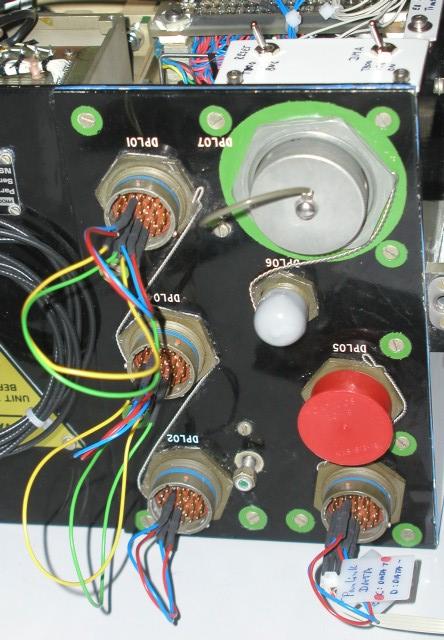
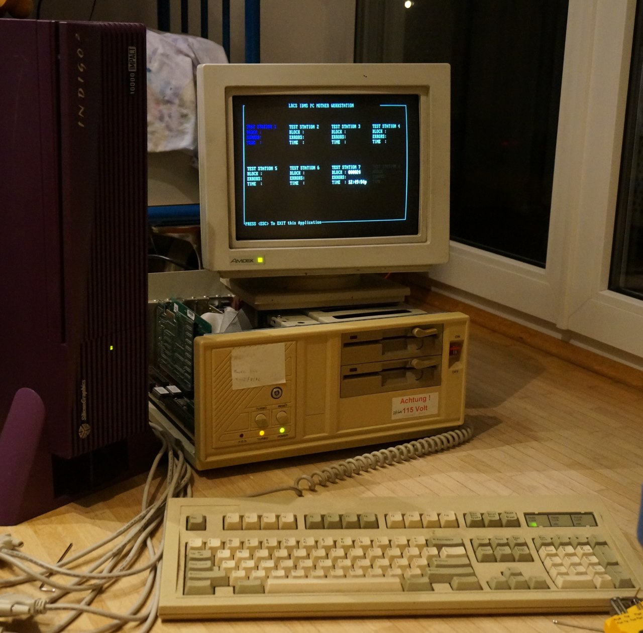
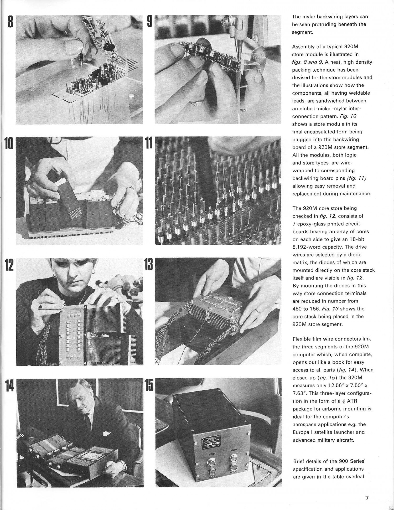
Generated by Erik Baigar on SGI/I2, 5/27/2017, viewed times. Impressum
& Datenschutzerklärung: HIER.